Building and Assembling a Wood-framed Panelized Yurt: the Basics

I also write DIYs for Instructables.com and just posted one about the yurt. You can find it here: Building a Wood-Framed Panelized Yurt. I entered it in their Tiny Homes Contest so if you like it, please vote, thanks! Voting ends October 1, 2018. I need a new camera. 🙂

LastPanel

Meanwhile, I’ve been posting more on the YurtYaks Facebook page than I have here, so if you’re curious about the rafter installation and the roof panel assembly, head over there! I’m busy finishing up the book, so will be back soon!

YurtBookCover2

Thanks for stopping by! Photos copyright ©2018 by Robin Koontz.

DIY Radiant Floor Heating System

This is about installing radiant floor heating in a slab floor system. While it was done as a new house was being built, in my last house I poured a concrete floor on top of a wood framed floor system and could have put radiant heat in that as well.

Pex-Plan

I obtained a design for the entire system from Supply House where I bought all the parts. They will provide, free, a layout according to your specs and also give you a list of parts you’ll need for the heating system. You can also download a free program from Uponor and also read more information than I will include here.

I opted for a single pump, single zone system for our 980 square foot little house, but opted to have each room a separate system zone that could be controlled by shutting down the water supply. For larger spaces, they would recommend more than one zone with a pump and thermostat for each.

First step was to install a vapor barrier and then insulate. I used extra (rigid) insulation – R15 – to encourage the heat to go up, not down into the dirt.

Pex4

Next I added 6×6 welded wire fabric (WWF) aka concrete reinforcement wire and used that to tie down the pipe. I bought a 1,000 foot roll of 1/2” pex pipe. You can get smaller rolls, but no way did I want any connections under the concrete floor. The pipe is very unwieldy especially in a coil that long, so I built a big spool for it and added dolly wheels so it could follow me around as I unwound pipe. The same contraption came in handy later when I wired the house.

Pex8

I used zip-ties to tie down the pex pipe. Here are a few photos of the process. We took a lot more photos so we could remember exactly where all those pipes fell. I did not want to be nailing down a plate for a closet and poking a hole in my heating system.

Pex9

Pex5

Then I installed concrete doobies and tied down rebar, just standard practice for a concrete floor.

Pex3

Pex-1

I also tied all the pipes together and pressurized them. I wanted to make sure there were no leaks before that 4 inch thick concrete was poured on top of them.

Pex-2

After the floor was poured, I moved on to building the house. Since I worked pretty much alone and at my own pace, it was a couple of years before it was time to set up the heating system. I built a large utility core with plenty of room for two water heaters as the one designated for the floor would be set low, and space for me to get in and make adjustments. The option for an instant-flow water heater was there, but I didn’t want to spend that kind of money. I just got a standard 40 gallon hot water heater for a couple hundred dollars.

Pex12


The heating system consists of a thermostat which is wired into a relay transfer switch. I located the thermostat in the living room, which in our house is a central location. Since I was building the house from scratch, I could easily run the wire in the walls and over to the utility core. The relay tells the system when to start up. A pump kicks on and water runs from the water heater and into the floors. Water from the floors runs back into the water heater. If you can see the numbers on the gauges in the photo, the water going out is about 100 degrees and the water coming back is about 80 degrees.

Pex11

The first issue once everything is connected up is getting the air out. If you troubleshoot a radiant floor system by googling, “air in the lines” comes up as the #1 issue. I futzed with it until the air was gone. The second issue was the size of the pump. I trusted the supply house to provide me with a pump adequate for the system they designed, but that didn’t happen. The pump has to be strong enough to deal with the resistance in over 900 feet of 1/2” pipe. You can determine the needs by calculating the feet of head, which I did and the pump came up short. I ordered two sizes up and the system is now working beautifully. The pump doesn’t kick on very often and the house stays evenly heated, ranging from 69-72. I use a Cen-Tech infrared thermometer to see what’s going on.

Pex13

Meanwhile, the pets have figured out where the supply pipes are and love to lay down on the nice warm floor.

Pex14

With me doing all the work, the total cost including everything involved was about $1,700. We haven’t got an electric bill yet, but considering that the house is so warm and the water heater is well insulated, plus the water going back in is almost as hot as it needs to be anyway, we suspect we’re not using very much energy for this system. It is a wonder that at least in Oregon, there are no Energy Credits for putting in this efficient system. I hope to change their minds about that.

Happy winter!


An Easier Fit: Cutting and Installing a Visqueen Vapor Barrier

I am still plugging along on my DIY house construction project in western Oregon. I’m just about ready for drywall at last. Meanwhile, Oregon code requires that there be a vapor barrier. This requirement could be accomplished also with a paint barrier applied later in the construction process. But since I have always used visqueen as the vapor barrier, I was going to continue with what I knew. By the way, this is how you spell visqueen – it’s not visquine.

Visqueen presents some real problems in installation. It doesn’t always lay flat, it tends to “squirm” about when trying to attach it, and it doesn’t cut easily (in the 6 mil). Cutting for openings usually results in a much larger opening than is necessary and too large to seal successfully.

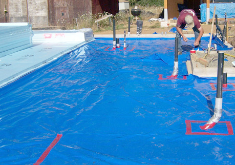
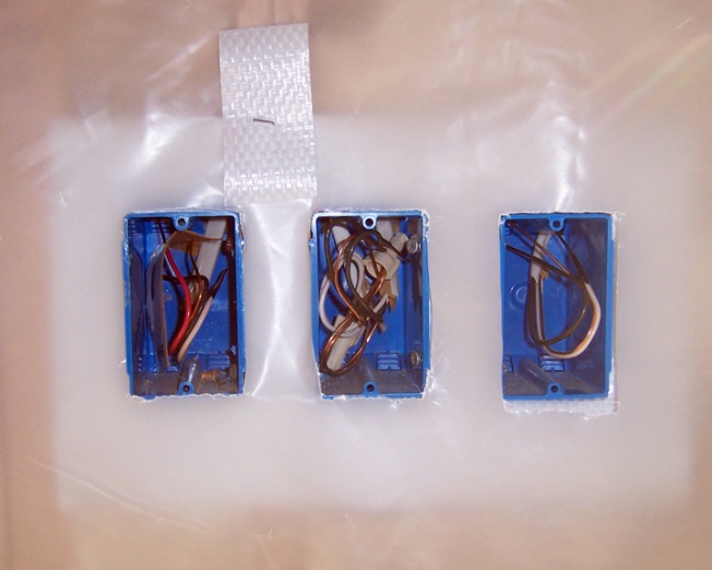
This prompted me to come up with a simple gasket that could be cut tightly around a light or receptacle box or ceiling fan housing. I cut the gaskets from roof covering material originally meant for my carport – glad that I found a use for that stuff, as it was an epic fail as a roof covering material. The gaskets could be rapidly cut out using standard size sheets and an electric receptacle box sized piece of wood to cut out the “opening.” This gasket could be quickly placed over each box. After the visqueen had been placed on the walls and stapled adequately (not excessively), the openings could be cut out with a little less care. The gasket and visqueen were then bonded together with Flex-Seal into a well sealed opening in the vapor barrier.

VaporBarrier3Blog
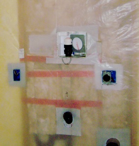
You can see the roofing material behind the boxes in this photo.

VaporBarrierBlog
My cut out for the receptacle box on the right was a little off, but saved by the background layer of roofing material which was easily cut tight to the box.

What it’s all about
Vapor diffusion is the movement of moisture in the vapor state through a material. It is a result of a vapor pressure difference (concentration gradient) or a temperature difference (thermal gradient). Vapor barriers, these days more accurately referred to as vapor diffusion retarders, are installed to reduce how much water vapor can get inside a building. Vapor diffusion retarders are installed throughout the structure and sealed up.

Vapor retarders are measured in “perms” for permeability. Class I vapor retarders, with 0.1 perms or less, are glass, sheet metal, rubber membrane, and polyethylene sheeting. Class II vapor retarders have between 0.1 and 1.0 perms. They are unfaced expanded or extruded polystyrene, 30 pound asphalt coated paper, plywood, and bitumen coated craft paper. Finally Class III vapor retarders, with greater than 1.0 and less than or equal to 10 perms: gypsum board, unfaced fiberglass or cellulose insulation, board lumber, concrete block, brick, 15-pound asphalt coasted paper, and house wrap.

The type of construction and location of the building factor into if vapor diffusion retarders are needed and if so, how much. In milder climates, painted gypsum wallboard with a plaster coating may be all that is needed to prevent moisture from diffusing the building. Higher-per vapor diffusion retarders are needed in more extreme climates. They also do the best job if installed on the warm side of the structural assembly – which means close to the interior in cold climates and close to the exterior in hot/wet climates.

In southern climates a combination of an air barrier and vapor diffusion retarder can help keep the humid outdoor air from entering the building cavities. The material is usually installed around the perimeter of the building just under the exterior finish material. Sometimes the air barrier/vapor diffusion retarder IS the exterior finish.

If an existing building has moisture issues because of a lack of proper vapor diffusion retarders, numerous layers of “vapor barrier” paint can be a way to improve the situation.

In any case, vapor diffusion retarders or air barrier/ vapor diffusion retarders won’t do a good job unless they are installed and inspected carefully and all leaks are sealed. The more extreme the climate, the more crucial it is to provide a perfect installation job.

If you want to read more about all of this, check out this article from the Building Science Corporation by Joseph Lstiburek, Ph.D., P.Eng.

Be sure to check out my book about building a bridge. It includes some cool ideas that apply to other projects, like how to put a really tall post into a deep hole when you aren’t that tall. Here is the link:

Building a Small Cable Suspension Bridge with the Cable Locking System

Images, diagrams, and text copyright 2014 by Marvin Denmark unless otherwise noted. Please do not copy and post my content anywhere without my permission. Thank you.

Size Matters.

My business card read, “SMALL HOMES, SOLAR ENERGY” in big letters in the upper left corner. My goal was to build small, energy efficient solar-heated homes. It was 1985, when the country was dealing with an ongoing energy crisis – imported oil prices were high and everyone said that Americans in particular were using too much. So it seemed that my plan to build smaller more energy-efficient houses would work.

It didn’t. I did design and/or build a few small solar projects. But as for new homes – people just didn’t want to build a small house. They figured that the more square feet, the less cost per square foot to build! The long-range costs of heating and cooling huge houses mattered little. And as time marched on, oil prices went up, came down some, and went up a little higher. People got used to the costs, amazingly enough. Most people continued to build houses much larger than anyone really needs. So my ideal to design efficient housing pretty much fell by the wayside.

In 1995, I was invited to build a house in Japan. That’s another story for later, but what I’m recalling is the size of the apartment that I lived in during the four months I was there. Here’s a sketch I made of the floorplan (the elevations are at the end of this post):
ApartmentDesign1-loresThe apartment was in a two-story building with 10-12 apartments on each level. Each apartment was meant for a single, couple, or even a couple with a small child. It was an incredibly small space, at approximately 225 square feet with a loft sleeping area. But it was not that bad, with a more efficient use of space than small apartments in the U.S., usually called studios, and usually reserved for cities with high rents or singles and couples just starting out. You’ll note a similar design in a travel trailer, a place that few people in this country would want to live in for an extended period, unless they had no choice.

But Japanese have the choice, and most choose to use efficient living spaces rather than build gigantic houses with multiple bathrooms, bedrooms, formal dining rooms, and all that. I suspect most Japanese men would laugh at the thought of a “Man Cave.”

I’m building a house for myself and my spouse at the moment. It’s less than 1,000 square feet, but seems huge to us. I tried to design something that was practical and comfortable with unique elements such as a gable-end roof venting system and radiant heat flooring. There’s a fun little breakfast nook and a recessed entry to accommodate the need to shed wet raingear before coming inside the house, a common problem in western Oregon. And there are other things. But, alas, it seems the first question many ask about our new house is, “How many square feet is it?”

ApartmentDesign2-lores
ApartmentDesign3-lores
Thanks for stopping by! Be sure to check out our bridge book. It includes some cool ideas that apply to other projects, like how to put a really tall post into a deep hole when you aren’t that tall. Amazon has the book on sale for about $13.00 right now. Here is the link:

Building a Small Cable Suspension Bridge with the Cable Locking System

Images, diagrams, and text copyright 2013 by Marvin Denmark unless otherwise noted. Please do not copy and post my content anywhere without my permission. Thank you.