Replacing the decking on a suspension bridge

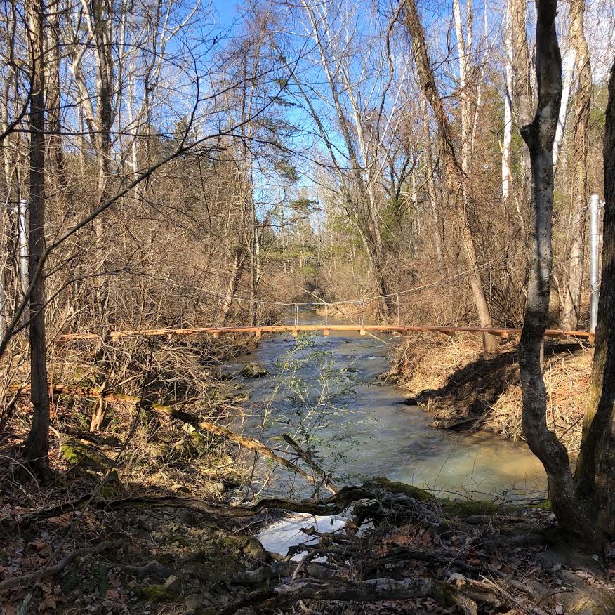
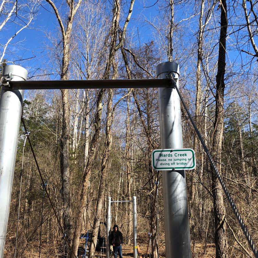
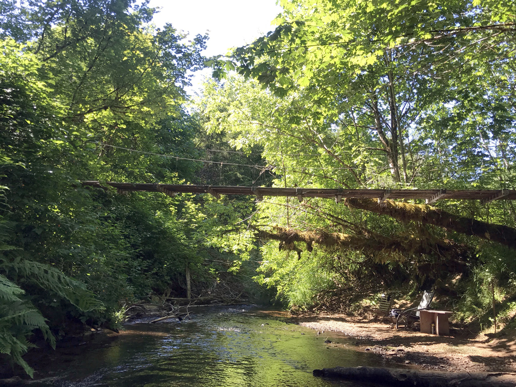
February 25, 2019 was a very bad day for our 80′ suspension bridge that we built in 2005. Part of a large maple tree that was weighted down with heavy snow decided to break and fall directly on one of the support posts on the other side of the creek, bringing lots of other trees along with it. Once it thawed and we could clean up the mess, we assessed the damage. We had to replace the post and raise the bridge again. You can read about that here. The next step was to replace the decking and adjust the suspender cables.

This summer I finally carved out time to get it done. To note, the old decking had already been recycled three times. The untreated fir was originally pulled from a deck from a remodel job and used as a deck in front of my shop. It stayed there for about twenty years before several boards got so bad I decided to pull the whole thing apart and save what was still good and send the rest away. By the way, I used the concrete piers from that deck as foundation for our yurt, which you can read about here.

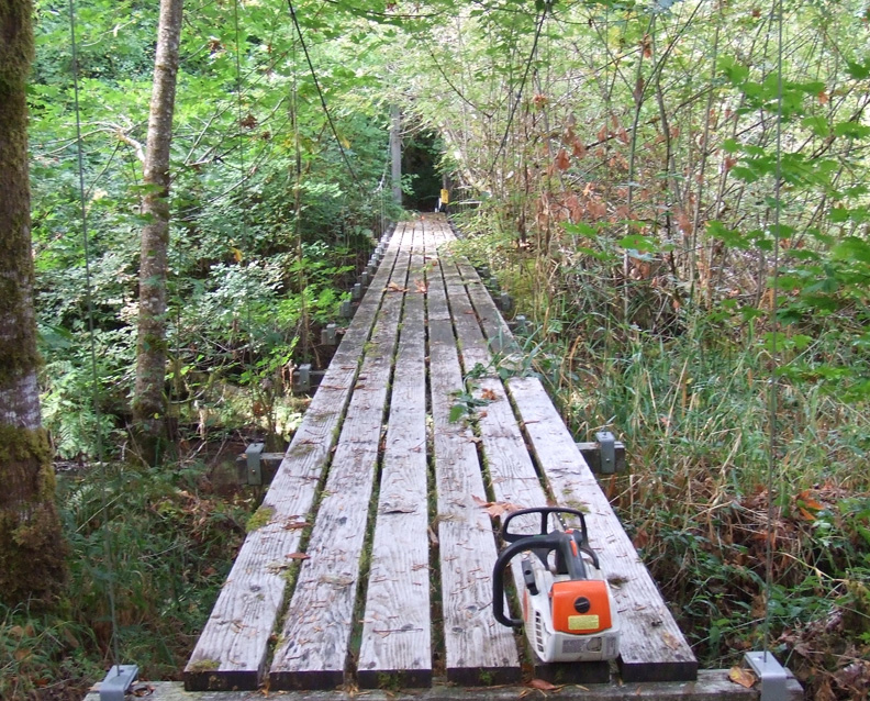
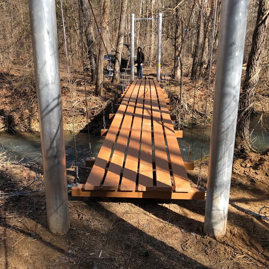
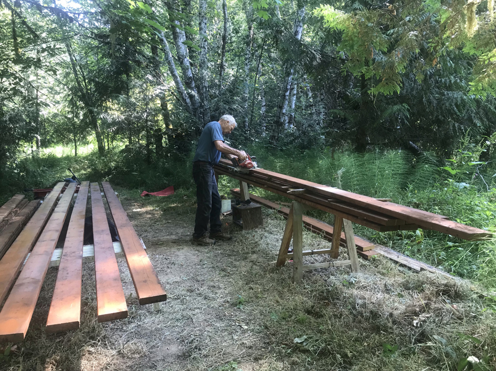
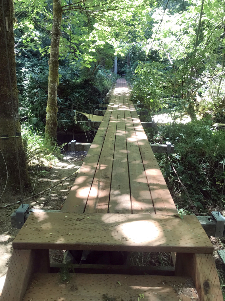
The decking held up very well all things considered. We scraped most of the moss off and usually kept the leaves raked, but it was already overdue to be replaced when the bridge was hit. While we originally hoped to use some kind of metal for our “final” deck, we decided to use pressure treated dock boards. I put a coat of water sealant on all sides just to give the boards a bit more protection.

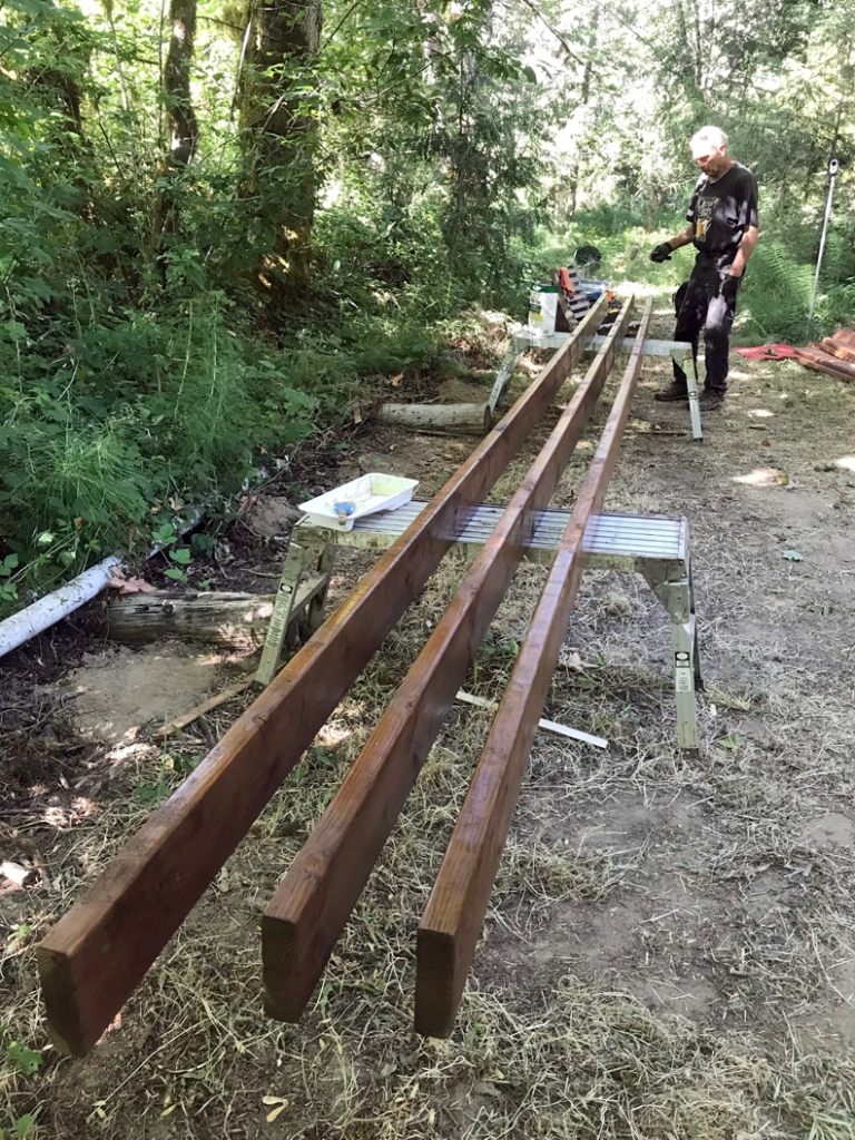
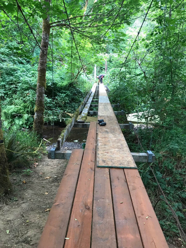
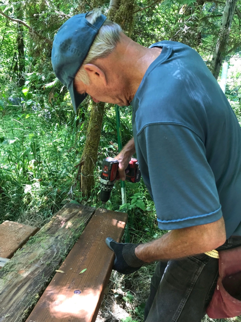
The original decking consisted of six 2×6 boards spaced about an inch apart. I decided to change both the number of boards in the span and the spacing. This made for a more than adequate deck to cross and would help keep moss from getting between the boards. But it created some difficulty in the replacement process. Instead of just removing boards and replacing them, I had to start over and work carefully while working about 12 feet up from the creek bed. I wasn’t as young as I was when I installed the first deck in 2005…

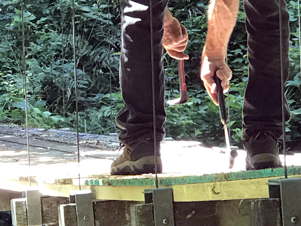
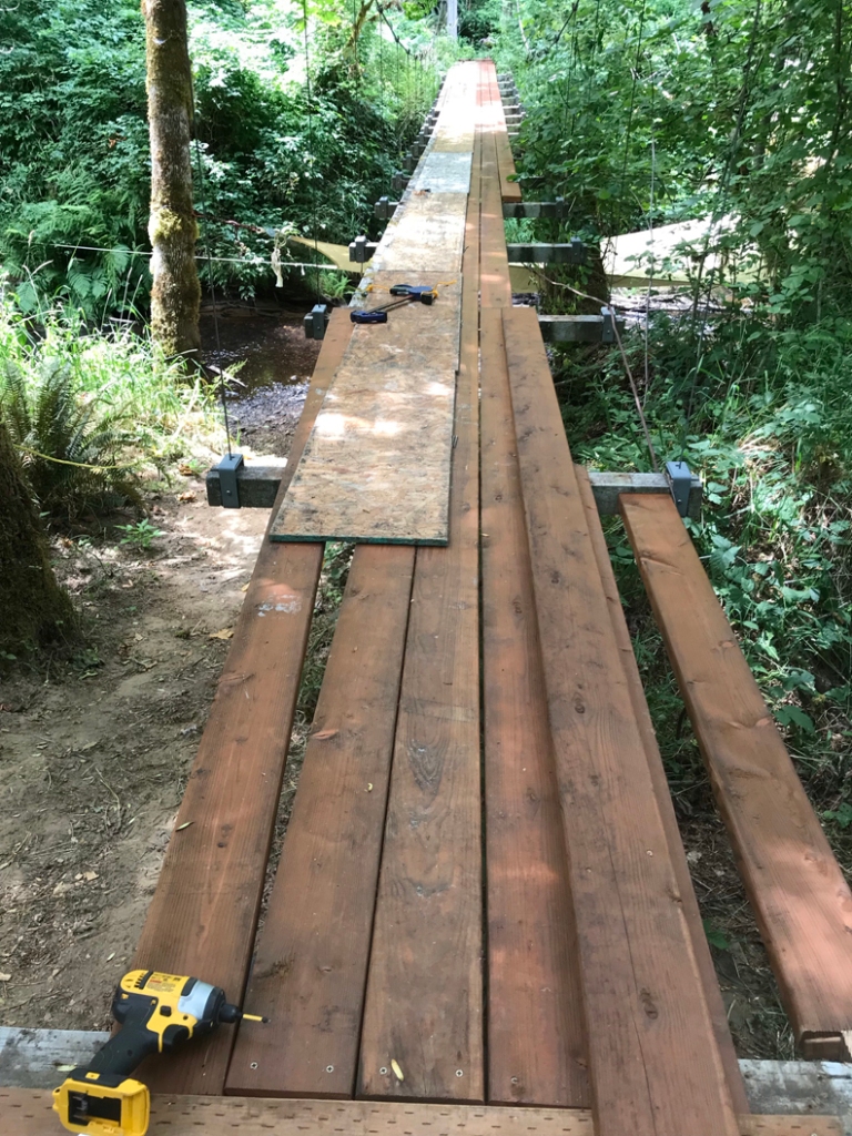
The hardest part of the process was removing the old decking. The metal screws had rusted because of the interaction between them and the pressure-treated support beams. So, a lot of them didn’t come out without a fight.

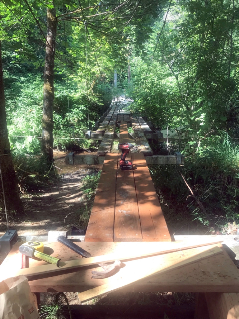
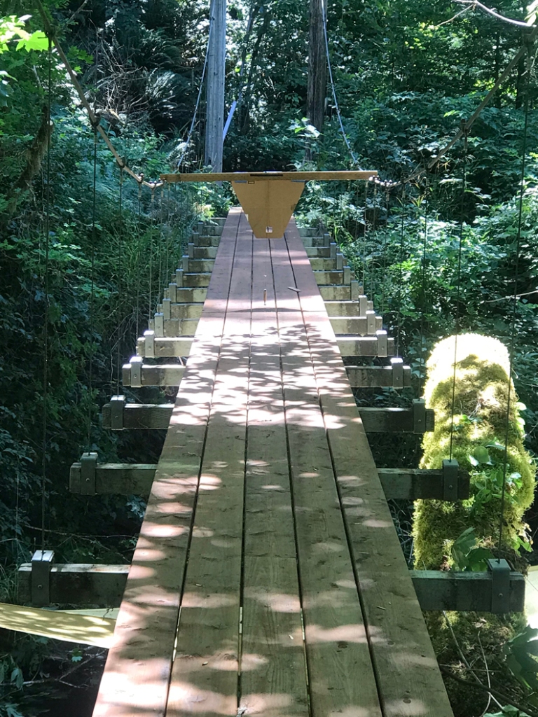
At first, I planned to build as I moved along, but soon decided that it made more sense to do the center run (of 5) first, then down one side and then down the other, using plywood planks on top of the old damaged decking for stability. I cut the pieces in pretty much the same pattern as before.

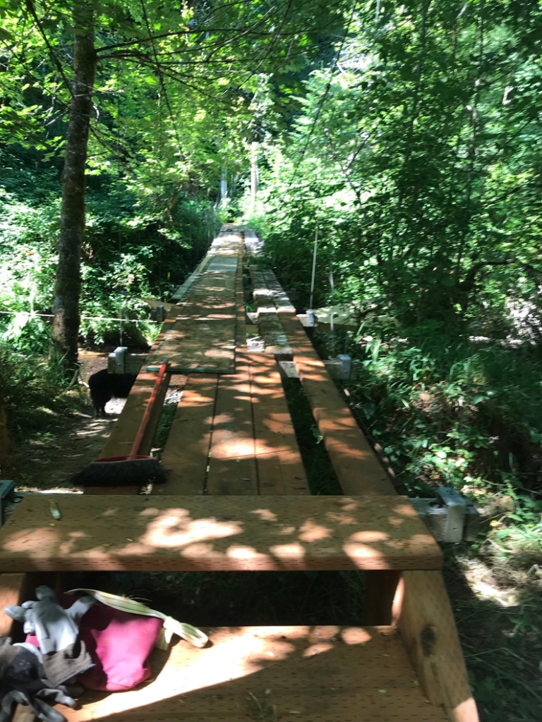
Once I got going, the process took about a week of not working full-time. I worked pretty much alone, though Robin did most of the treatment of the new boards.

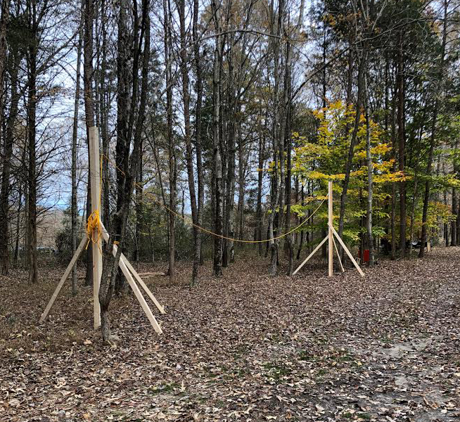
Once completed, I needed to level up the deck. I had waited until this work was done to really tighten things back up after we replaced the post that was destroyed in the storm. The deck had a twist in it, partly from the hit and partly from hanging sideways for about nine months.

Because the post was broken in half and the deck twisted sideways, it pulled the opposite post inward. This caused the suspender cables to misalign. Once the posts are brought into alignment and opposing suspenders are both vertical, then tension can be adjusted to bring the deck up and level.

Looking across the support beam, the cable in front is vertical but the one across is “leaning.” This is an “after” photo; I forgot to take one before I fixed them.

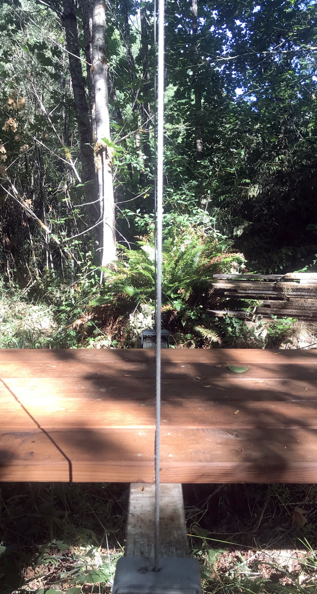
I devised a “level” of sorts by taking a piece of wood long enough to ride over both cables, a wooden level. On that level, a piece of cardboard was securely attached. A line being perpendicular to the bottom edge of the “level” wood piece was then drawn across the cardboard to create a center line of the level and cardboard. It was boldly marked so it could be seen from a distance. A plumb-bob was then attached directly on the centerline. When the deck was adjusted so that the plumb-bob line matched up to the line drawn on the cardboard the deck would be level. I adjusted the deck by tightening the turnbuckles. You can read about that process here.

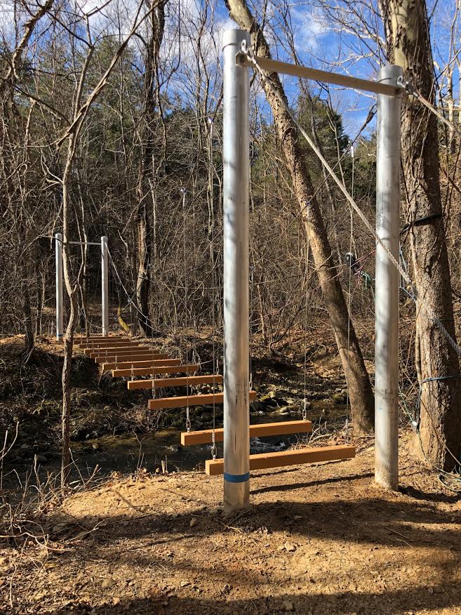
So, in all the pole was replaced, the steps were replaced, the decking was replaced, the suspender cables realigned, and the deck was leveled. There are not many big trees left that are aimed at the bridge, but we’ll see what nature brings next. Hopefully we’ll be ready.

The bridge helps to shade our favorite beach spot in the summertime. It’s hard to believe that little creek gets up to about one foot under the bridge during flood season, but it does!

Thanks for stopping by. Be sure to check out our books about building a yurt or a small cable suspension bridge. The links to purchase are on the introductory page:

Introduction to Wildcat Man

Images, diagrams, and text copyright 2013-2021 by Marvin Denmark unless otherwise noted. Please do not copy and post my content anywhere without my permission. Thank you.

Book-inspired Suspension Bridge in Virginia

We were delighted to finally receive photos of a suspension bridge that was inspired by our book, Building a Small Cable Suspension Bridge With the Cable Locking System.

1-7

According to the builder, Mo Goldman, the bridge is just under 40′ feet in length and 4′ wide (basically half the length of our bridge) and is located in Virginia just outside of Charlottesville.

1-5

The posts are aluminum, 13′ in length, 6″ round with 1/4″ thick side walls, easy for two guys to carry. The post holes are 3′ deep and about 2′ around; the posts are placed on a concrete footer prior to pouring around them. Everything was hand-dug and poured because they were limited to access with a Polaris on one side.

It was fun to see that Mo set up a temporary cable to move materials across. That’s how we moved our gravel for the opposite side, one bucket at a time. But Mo took it further and carried the posts, other materials, plus wheelbarrow and even himself across their “zip line.”

SetUpStringers

Mo also followed the idea of setting up the catenary curve between two trees/structures located away from the creek to plan and build the cables and stringers on dry ground.

MoGoldman

Mo didn’t use our cable-locking system, but instead used a system often used for this type bridge – an appropriate length “eye” bolt placed in a drilled hole in the beam. The suspenders were then connected with a chain connecting link, which uses a threaded portion mating to a free spinning nut to open or close it.

He wrote to us about the bounce in his bridge which was more than he expected, though not a big deal. I noticed that he paid attention to harmonic resonance in the arrangement of the stringers so they were assumed off the “nodes,” so wondered if the decking material he used could be partly responsible (a suspension bridge is going to bounce, that’s a given). He used a material called Trex, which is a deck material made from recycled plastic and wood fiber. Trex tends to flex more than standard lumber does. We concluded that he needed to stiffen the deck, so now he is working on some ideas.

1-8

Mo even put up a sign on his bridge similar to ours and inspired us to remake our sign so that it names the creek, too. We hope others who build a bridge based on what we did will also send us photos and notes about their building experience.

Meanwhile our book is available in paperback and as an ebook via Amazon.com.


A Conflict between treated wood and metal parts

Pressure treated wood is a popular product for outdoor construction, i.e. bridges and decks. The chemicals (including chromated copper arsenate – CCA) that were used to treat wood in the U.S. and perhaps other countries were revised in recent years to remove at least some of the potentially harmful properties. The new formulations did help with the environmental risks, but they caused new problems for construction. When wood treated with the new chemicals was exposed to metal parts, the metal tended to corrode, even moreso in water contact environments, in only a few years. The pressure treatments I’m talking about are alkaline copper quaternary (ACQ) and copper azole (CA), which are both active corrosion materials.

So, the experts started recommending using galvanized steel or stainless steel for any metal parts, i.e. connector plates, joist hangars, and fasteners, that came into contact with pressure treated wood. Galvanized steel or stainless steel would withstand the chemicals for a while. So at least, the corrosion rate would be slowed down.

In my experience in remodeling, and specifically rebuilding decks, I found that some structures that had used ACQ or CA showed exactly how corrosive the treatments were. Galvanized steel joist hangers were nearly destroyed in only a few years.

I had this concern in mind when I built my suspension bridge. The cable locking system parts are hot-dip galvanized steel. But I also added a padding-wrap made of a bituminous material to add more protection between them and the painted (another layer of protection) pressure-treated beams that supported the bridge. Maybe I over-did it a little, but I like the things that I build to outlive me.

In building our new house, I ran into the problem again. In Oregon (and I’m guessing other states in the U.S.) it is required to install foundation anchor bolts in the stem wall foundation. These are to tie the house to the foundation. The bolts go through the pressure treated wooden plates and are secured with nuts. I had the issue again of metal making contact with pressure treated wood. I used ungalvanized (standard, but oversized to 5/8″ vs 1/2″ bolts) because I’m not convinced simple galvanization is the answer anyway. I opted to protect the bolts with a sleeve that I made from polyethylene tubing (5/8″ interior) material.

Bolt1

The bolt came through the hole in the pressure treated plate…

Bolt2

and then I used a water impervious roofing material tab…

Bolt3

before adding the galvanized steel plate.

Bolt4

At the completion all metal was completely isolated from the treated wood.

Thanks for stopping by! Be sure to check out our bridge book. Amazon has the book on sale for about $12.00 right now. Here is the link:

Building a Small Cable Suspension Bridge with the Cable Locking System

Images, diagrams, and text copyright 2013-2014 by Marvin Denmark unless otherwise noted. Please do not copy and post my content anywhere without my permission. Thank you.