I’ve always been interested in suspension bridges. But, since I grew up in flat country in central Texas, there were no examples I could look at. So it’s difficult to frame a time that bridges became more than just an interest.
It was probably when we purchased our property in western Oregon. A fair sized creek bisected it almost in two equal halves, making the half across from the home-site inaccessible without swimming across the creek. Plus, that half was on a rising bluff above the creek and now contained a replanted forest.
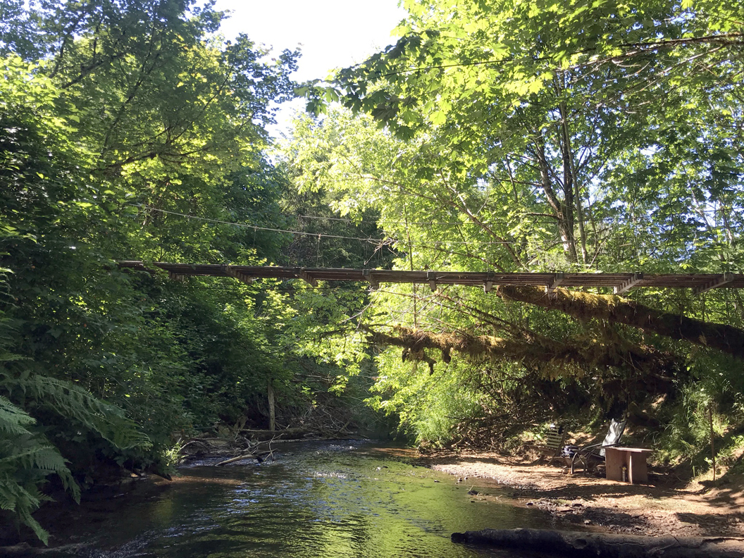
I pondered putting in a “vehicle” bridge. The problem was, we didn’t have that amount of money, having “just bought the farm” and were broke. But we had a more pressing issue that required access across the creek. The farm had always gotten its water from a spring across the creek and up that hill, and it needed to be easily accessible for maintenance and other issues. We needed access summer or winter, no matter what the weather or height of the creek. So, I decided to build a suspension bridge.
Humans have always built bridges. As soon as they moved from one continent to another, upon finding suitable land, they set out to make it theirs. If there was water to cross, they either built boats, a ferry, or a bridge. Early bridges would have been constructed from all natural materials. The main cable would probably be a thick, lengthy vine, or rope that was woven from fibrous plants, along with the same for the dropping “cables” (suspenders). Posts would have been strong, durable, rot-resistant trees. Cross beams and deck planks also came from trees and branches, or more readily available bank-side trees. The skills and construction knowledge would have been passed down generation to generation. One family could have been known as the bridge builders. Skills would have been honed and maintained by the constant necessity of maintenance or damage repair.
Since the Industrial Revolution, materials technologies have brought us a wide array of materials that suspended bridges can be built from. For example, at one time some bridges were built using chains or steel rods with an eye on each end linked together. Methods of construction have followed the materials knowledge and then leaped ahead to push the materials to new “limits.”
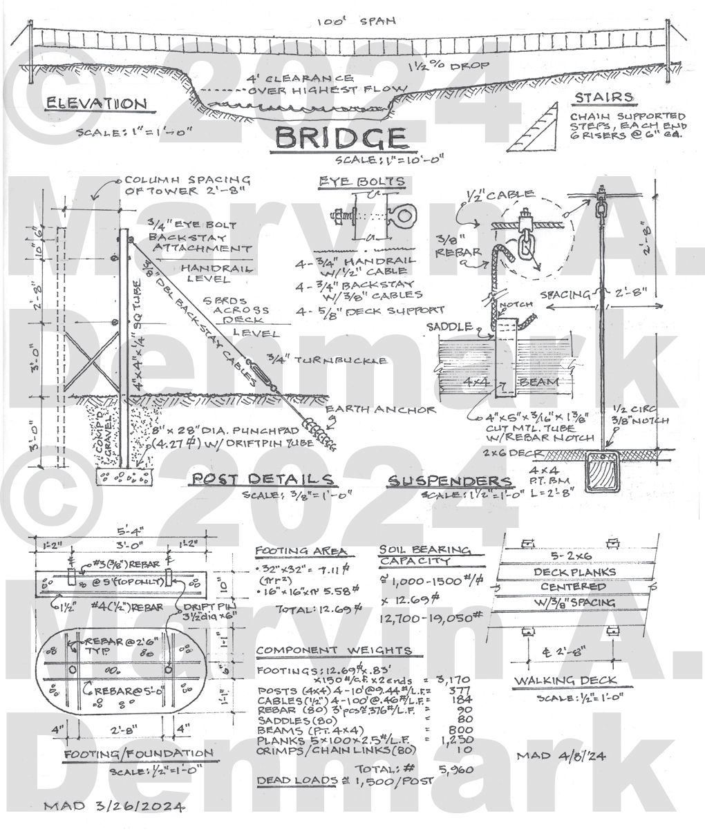
My bridge is based on time-tested materials and simple methods of construction much of which can be built and assembled off-site. All of the materials are ubiquitous throughout the world; you can pretty much find them in any corner of any country. I took a cue from Bridges to Prosperity: try to only use materials that can be sourced readily to where you are building your bridge.
I am going to go through each portion of this bridge as depicted in the drawing. This will be done in an order as any builder would follow, after having a design/plan. I’ll begin with the foundation, then I’ll get into the support system which includes the posts/columns. Next come the cables that span between the posts, followed by the dropping “cables” that hold up the deck system (this design is using rebar for the dropping cables). Next I will discuss the beams that the deck planks will fasten to, and finally the planking itself (the walking deck).
Over the next few months, I will publish all of this information with photos and illustrations right here on this blog. I’ve already begun work on the bridge and will post photos showing the progress. Once the bridge is completed, my partner Robin Koontz and I plan to put it all into another book. That way, readers will be able to get all the information they want free, from this blog. And, if they want something put together to refer back to, they can also purchase the book.
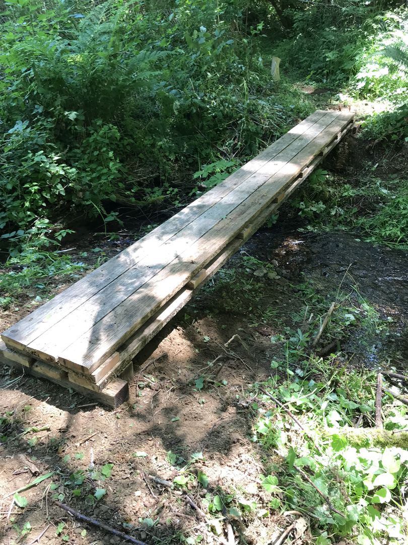
A little bridge I built to get to the new bridge site. This creek doesn’t flood like Wildcat does.
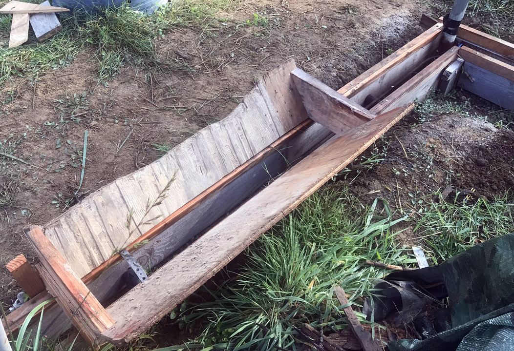
After years of other stuff getting in the way, I have finally begun work on a new suspension bridge. The new bridge will be similar to the first only in that the parts will be constructed off-site. The new bridge will have a different connection system as well as a different way to anchor the posts. It will have a hand-rail system, too. That’s one reason I am building it – to try a different approach to building a bridge. Plus we’ll have a complete hiking circle on our property on both sides of the creek.
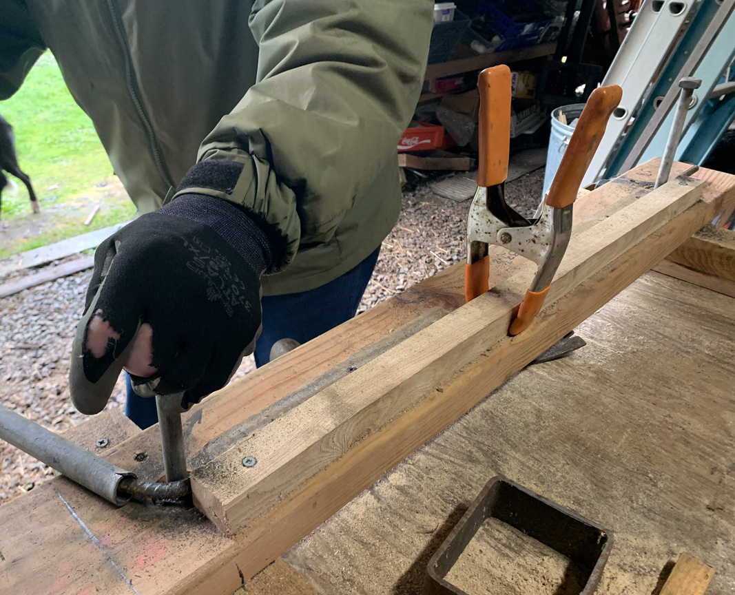
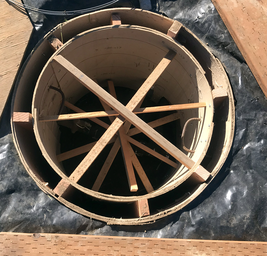
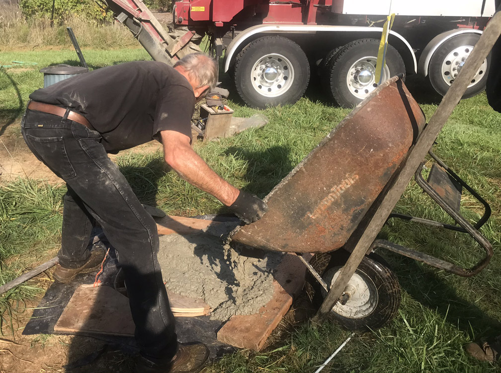
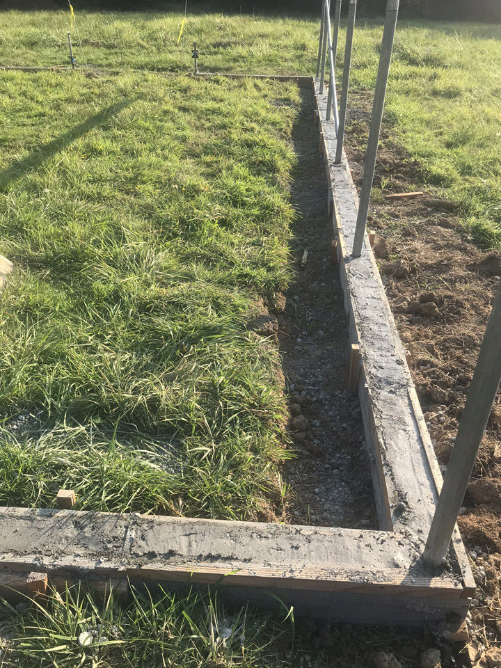
I plan to continue the project right after I recover from my second knee-replacement surgery. I’ve have already cleared the two landing sites and built several components for this 100-foot long bridge. I’m using metal posts this time and they have been cut to length. The biggest job after the prep work will be planting and backfilling those posts and anchoring them.
So, the only unknown is, will we publish a book about the new bridge? Unlike our first bridge, this time we’ll have a ton of photos. As explained in Building a Small Cable Suspension Bridge, we weren’t really thinking “book” when it was constructed and our camera used floppy disks and film. This potential book could have far more illustrations of the process.
But frankly, the process isn’t all that complicated. It could just be a blog post, right? We had a couple of reviewers suggest that for the first title. But here’s the thing: should we write and publish the information and instructions for free? It appears that a lot of people have come to expect writers, artists, photographers, and musicians to just give it to them for nothing since they already pay to have internet access. Creators should just give their creations away while these same people demanding free content punch a timecard and get paid for their work, right?
That makes no sense to us. Maybe YouTube with some annoying ads for those with a free account would produce a little beer money. And people who love to have a book for reference (and are happy to pay for it) would have the option to buy one. Okay, that’s if Robin will do most all the work, because I sure as heck don’t have the time. I’m too busy building stuff (or planting trees)!
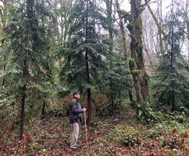
The bridge builder admiring the redwood trees he planted across the creek in 2004
We’ll think about it. Meanwhile, belated thanks for the other many positive reviews we’ve had for our little bridge book. Over 2,100 copies have sold to readers all over the world. We think that’s pretty cool. And, after all, books are forever. We hope.
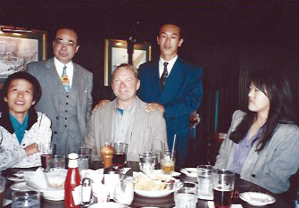
At the beginning of 1995 until almost May 1995, I was in Japan to instruct Japanese carpenters and assist in building a house. Introduced through a friend at the time, I was asked by two architects (a couple who were designing houses for Japanese clients) if I wanted to go to Japan to work on one of their current projects. It was to be an American styled house using all US products. The arrangement was that I, along with a second carpenter still to be chosen, would work as employees for the importer in Japan. There was a complementing exporter here in the US that would supply all the materials.
In US, a first meeting with the owner, left to right: architect, client/owner, me, head carpenter, American export representative.
It was an intriguing idea and I thought three months (that is as long as you can stay without a special visa) wouldn’t be that difficult, so I agreed.
With all of the materials and products being sourced in the states and then loaded on containers to be shipped out of a port here to some port close to the project, there was potential for problems. But that wasn’t my problem; at least not in that moment.
There are a myriad of problems that can come up in building any house project; what will the weather be, what is the access into and around the work, what kind of restrictions are there within a neighborhood, what permits and inspections will be needed, as well as others.
Then, the general contractor has the responsibility to purchase and arrange for the delivery of materials in a sequential and timely manner. Subcontractors have to be brought through the project at the proper stages and laborers and carpenters have to proceed on the work in a coordinated manner. And then there are client changes (change orders: either adding something or subtracting) to the project. Any hiccup and the whole job can come to a halt.
Still in the states, at a meeting with the architects and the US exporter, I said, to the representative for the export company, “You know you are the acting general contractor here”. I was sure he was aware of his position but I wanted to impress on him the importance.
My business card that a printer friend translated into Kanji for me.
Periodically, preceding departure, I and the other carpenter received information on specialty products and updates to the drawings. When I received the drawings done by the truss company, less than two weeks before departure, I immediately saw a serious problem. The drawings showed at least four different heights (spring height) the trusses were rising up from, which meant different wall heights, not indicated on the architect’s house drawings. I contacted the architects and told them of the problem. (I joked at the time that if the trusses arrived incorrect, I would just tear them apart and stick frame the roof with the pieces, knowing full well that wasn’t possible.) It came down to: I might not know until the trusses arrived in port if they had been corrected. They did arrive corrected.
A note about building in the US: the system of building houses here is called western platform framing. It has been used since after the Second World War, and could be credited for the rapid housing construction of the 50’s and 60’s following the veterans returning home. These are site built homes with walls framed while lying flat on a “platform”, i.e. the first floor of the house. That platform can be established by several options of foundation systems, being a slab poured in place, or atop a stem wall foundation, or a basement poured below, or even a post and beam structure supporting that floor. The walls are framed all at the same height in order to build a new platform for the next story, or, to frame the roof.
We (carpenters) arrived in Japan several days before the first container was to arrive. Once in Ishinomaki, after settling into our apartments, we met with the home owners, the head carpenter, the import representatives and our interpreter. We had earlier met our interpreter as she was assigned to pick us up from a hotel we stayed in after arriving at Narita Airport outside of Tokyo. She had helped us navigate via high speed rail line our way to Ishinomaki.
Discouragingly, there was no previous plan for storage made for materials as they arrived, so they would all be “parked” in the small yard of the house as each container arrived and contents were trucked to the house site. Containers would come sequentially with the needed materials to proceed with construction until the next container arrived. I recall the first two containers arrived together, out of six containers total. In those first containers with lumber (structural) products an inspection had to be done and approved for use. Cabinets and trim skipped that process.
Having arrived in January, our work began in wet, cold and snowy conditions. With the foundation having previously been put in place, and the container contents having been brought to the site, we immediately got into the framing of the house. Things progressed smoothly with the crew of two American carpenters and three to five Japanese carpenters.
This is the Lunch and Break Room.
Not only were we building a house but additionally there was a 2 story office/shop for the house owner, who was an electrical contractor. It was a panelized structure, that is, all the walls end to end were made into some manageable length by an 8’ height. With the foundation already completed, the building went up quickly.
Things progressed reasonably well until about the fourth container. There were some shipping company problems, but mostly delays in filling the containers with the appropriate materials. One early problem was that the kitchen cabinets arrived well before any roofing materials. We stored the cabinets in their original boxes in the yard. But it was snowing on the day they were placed in the yard and even though told to clear all snow off, it was somewhat overlooked. Upon finally opening and inspection, there was luckily only minimal staining damage.
As we carpenters reached the end of our three month stay, the house was in the interior finish stage. The owner was disgruntled as he had hoped to be even further along. He had further disappointment because of a roofing material misunderstanding. The plans called for no specific exposure measurement for a slate style product, and the Japanese roofing contractor had wanted to put it down just as they would there. And, even though cautioned that he would run out of materials if he did, and with a compromise given (not knowing exactly what coverage we had with “any” measurement) on a greater exposure, it was still put down closer to his desires and we ran out. I tried to lobby on the side of the owner with the argument that there was no specific “exposure” measurement given, but in the end the owner had to pay for extra roofing materials.
At the end (of our employment) of the three month Visa period, I wrote a critique of the project/process for the Japanese importers. I had keep a daily journal of both notes and pictures. I had written down each day every problem, its source, the effects, and the resolution. The two predominant issues were not receiving needed materials in a timely manner, especially toward the end, and drawings that were confusing or not quite accurate or complete. Both of these are easily solved when the supplier or the architect is just down the street. That was not the case here.
With Japan being about fourteen hours time difference, and most communications done by fax, I had taken a laptop with me to solve this time delay problem. However, it stopped working a week after arriving there. And I could find no one to fix it, even though it was most likely manufactured in Japan.
I decided that I would stay an additional month to help deal with some outstanding problems to the finishing of the house. The last container was to arrive within that one month timeframe. Unfortunately that didn’t happen. For the house, one of the issues was the stair parts to complete its installation. While all the treads and risers had been in place for some time, none of the newel posts, handrails and spindles had arrived, plus there were specialty parts to make the two turns to get to the second story. I mocked up as much as possible to demonstrate the proper usage. The Japanese carpenters had expressed some trepidation about it all.
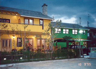
Even after staying an extra month, the house hadn’t progressed much due to shipping delays. But, it did get painted. Bright canary yellow. The interpreter said we need to call it the “yellow house”. And so we did. It stood out in the monotone neighborhood like a neon sign. I took a picture of it from about a half mile away. There was no “where’s Waldo moment”.
About four months after returning home I received a package from the owner. It was a photo album of the finished house. In the tsunami of 2011 Ishinomaki was the epicenter of the inland flooding and the “Yellow house” was enveloped in about three feet of water in the interior. But it survived.
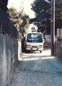
I returned to Japan at the very end of 1995 to guide and assist in constructing another house. This was a SIP (structural insulated panel) two-story house. It was a completely new construction for the Japanese carpenters. The only real framing to be done was the interior room dividing walls. Even the floor (structure) and roof panels were SIP. We were done quickly.
SIP house on the left, narrow street we traveled on the right.
Thanks for stopping by. Be sure to check out our books about building a yurt or a small cable suspension bridge. The links to purchase are on the introductory page:
Images, diagrams, and text copyright 2013-2023 by Marvin Denmark unless otherwise noted. Please do not copy and post my content anywhere without my permission. Thank you.
If you look closely at the far end of the bridge, you’ll see we also have a new puppy. Like his predecessors, he thinks the bridge is totally cool.
As of June 20, 2023, there are three softcover editions of Building a Wood Framed Panelized Yurt and two softcover editions of Building a Small Cable Suspension Bridge.
The yurt book has a black and white, deluxe color, and now a standard color edition. The standard color is priced at less than the original deluxe color edition and the deluxe color edition went up in price because of the price increases set by Kindle Direct Publishing.
The bridge book has a deluxe color and also, now a standard color edition. The price went up on the deluxe color edition. It is currently on sale at the old price, which is something Amazon did.
Nothing in the content changed in either book other than a new ISBN for the standard color editions, and some resizing of images in the yurt book to meet new production criteria.
To find all the editions and choose the one you want, find one of them and then click on “See all formats and editions.” Or just use these links:
Link to the deluxe color edition of the bridge book.
Link to the standard color edition.
Link to the black and white edition of the yurt book.
Link to the deluxe color edition.
Link to the standard color edition.
We hope this isn’t too confusing. It would have been easy if KDP allowed us to just switch from deluxe color to standard, but that was not an option. We may eventually phase out the deluxe color edition but we’ll see what the feedback is on the standard color. Meanwhile, we have begun building a new bridge and plan to publish a new book in the next year or so. Stay tuned!
Thanks for stopping by. Be sure to check out our books about building a yurt or a small cable suspension bridge. The links to purchase are on the introductory page:
Images, diagrams, and text copyright 2013-2023 by Marvin Denmark unless otherwise noted. Please do not copy and post my content anywhere without my permission. Thank you.
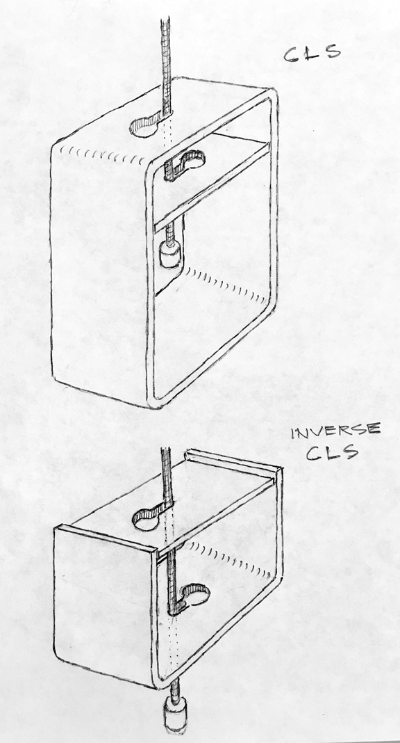
This is a re-post from 2018, with an updated drawing of the Inverse Cable Locking System.
Off and on we receive requests for the cable locking system (CLS); either the parts or for dimensions. As we have stated before, we could not produce/have manufactured, store and handle/ship the parts at a reasonable cost to the buyer, so we do not provide them for sale. While all of this information is in the book or in previous blogs, we thought we would try to break down the method for sizing of the CLS so interested bridge builders could use the information to have their parts manufactured close to home.
Refer to the drawing below to picture the description that follows.
The main body of the CLS was made from a section of rectangular steel tube of 4″ X 5″ outside diameter, the section being 1-3/4″ wide. The wall thickness was .17 of 1 inch, which is very close to 3/16″. The interior was therefore close to 3-5/8″ by 4-5/8″, which fits nicely with a 4X4 (nominal) piece of lumber. So that defines the main body of the device. [After my project, I now would recommend using a 4″ X 6″ tube for the extra room for maneuvering the cable during assembly.] There is a locking plate that fits inside of the main body. It is also .17 of an inch (3/16″) and is sized to fit just inside, at 3-9/16″.
The location of the keyhole is placed in this method: the keyhole is composed of a large hole with a smaller slot. If you picture the end of that slot as a hole of the dimension of the suspending cable, that hole would be placed in the exact center of one of the 4″ ends of the rectangular tube, the remaining keyhole would point towards one of the tube’s edges. The locking plate is treated similarly.
The dimensions for the keyhole are determined by making them slightly larger than the materials passing through. Since the suspending cable is 3/16″ the hole was enlarged by 1/32″, thus the hole was drilled at 7/32″. For the large end of the keyhole the dimension of the stop was the guiding size. The aluminum cable stops once crimped on measured 1/2″, which is enlarged by 1/16″ to allow for easy passage of the stop through both plates of metal. So that hole is drilled at 9/16″. There is nothing imperative about these drilled dimensions. If you use different materials than you adjust the holes accordingly.
For the inverse CLS, you simply need to cut off the bottom half of the 4X5 steel tube section. You now have essentially a section of steel C channel of 4″ width, with 2 1/2″ flanges. Now mirror-image this remaining half. You should have it placed beneath the 4X4 beam, cradling it. This changes the CLS from a tension device to a compression device, but the plates function in the same manner as before. All sizing remains the same. What does change is that you have to drill a 5/8″ hole (insert an anti-corrosion vinyl tube in hole) in the 4X4 beam so the suspending cable can pass through to access the inverse CLS.
Thanks for stopping by. Be sure to check out our books about building a yurt or a small cable suspension bridge. The links to purchase are on the introductory page:
Images, diagrams, and text copyright 2013-2022 by Marvin Denmark unless otherwise noted. Please do not copy and post my content anywhere without my permission. Thank you.
I think in the intro to my blog it says I have 50+ years of experience in carpentry/construction. A recent question posed to me about safety and being confident in what you build brought me to recall my “life” of carpentry.
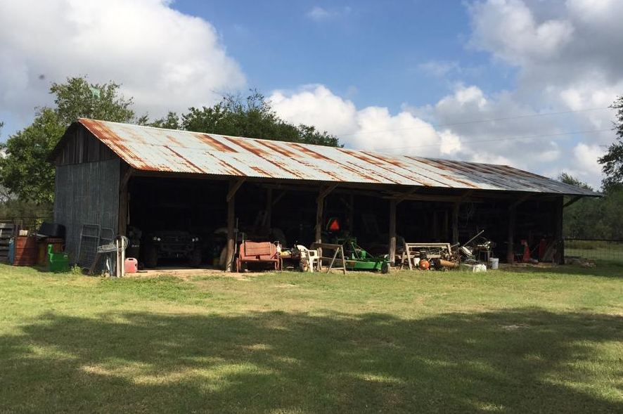
You could say it started when at the almost age of six, my family moved from one farm to another farm. This new farm had only a house, a wash house, a garage of sorts with a small attached workshop, an outhouse, and an old dairy barn. But it didn’t have a real barn*. So, my father set about building one. It was to be a pole barn about 40′ wide by 60′ long. At my age I wasn’t going to be of any help, but my two older brothers were, doing the grunt work, digging the holes for the power pole/posts to rest in. Also, my dad’s dad and an uncle assisted with the tasks requiring carpentry skills.
About a third of the pole barn was destroyed by a storm long ago; this is what remains, as of about 2016.
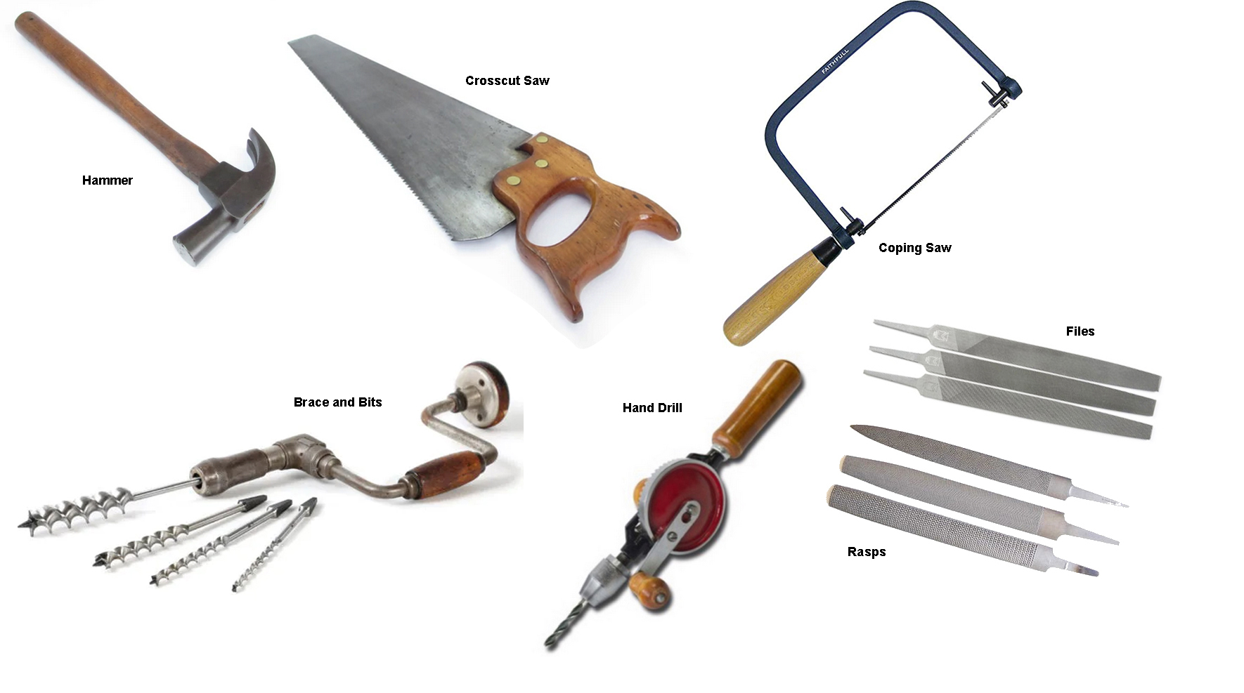
My grandfather was employed at a flour mill, but on the side he repaired chairs for people. He had a small workshop in the back of his garage. This was before power tools, so he had all hand tools: hammers, saws (crosscut and rip), braces (hand powered drills) and augers/bits, a hand held drill with bits, and files and rasps.
There were also tacks and nails, glue, plus other materials to repair the chairs. I still have this photo-image memory of chairs, some waiting for repairs and others waiting to go home, hanging overhead above the parked car in his garage.
Whenever the family visited my grandparents, I would head to that shop. Sometimes he would be available and explain the tools and how to use them. You could say I was hooked.
Back on the farm, I started making things of wood. Probably the earliest was when I was about six years old. My family didn’t have much money so toys were in short supply. We had one cap gun to play “cowboys and [indians]” (I can’t rewrite history). So that my cousin and I could “shoot” at each other, I started making wooden guns; cutting them out with a coping saw, then rasping the rounder shapes or carving with a pocket knife thus shaping out of the planks of wood, a replica, as near as I could, of a six gun. I think I made only two. The boards were not real thick so the cylinder wasn’t very round, but it looked okay.
Next I carved “Bowie” knives. They were small replicas, maybe 8” long, of that knife. They were sharp, although being of wood one would have to saw across your finger to affect a cut. But they had a point that would puncture.
Bowie knife.
When I was six or seven years old and just starting school, or beginning the second grade, I took one of the knives to school to show my classmates – my new friends. On the playground, when my teacher discovered the “knife,” she took it from me. She promised that I would get it back at the end of the year. I never saw it again. Ahh, but I had made more than one!
When I was older, perhaps 8 or 9, I had seen flat bottom boats on television. So I decided to build one. We didn’t have much scrap/or spare wood around so I found enough to build what resembled more a hog-feeding trough than a boat. It was long enough to get two small people my size in. I got it down to a cattle tank (pond) we had with shallow water at the edges. I coaxed my youngest sister to join me. We got in and it promptly sank. I didn’t know about displacement. I never got back to rebuilding it again because we had no more or enough wood. But I learned something, even though that realization was much later.
Then there were the times when I thought I could be an aspiring Native American (not that I knew anything about that life.) I was probably around eleven or twelve. I was always barefoot running down the path on our farm toward where a group of the Comanche tribes had once inhabited the land we now held. (Over the years we found many arrowheads, blades, scraping tools, and things we never knew the uses for.) I decided to make bows and arrows. Not having any knowledge of wood qualities, I choose willow, a prevalent brush, to make my bows from. I used the rasp to grind the branches down to the shape and thickness. I made several iterations that culminated in a laminated body, bonded together with something akin to shoe goo and bound with braided fishing line. I used fish line for the string.
Making arrows was a challenge. Finding straight branches was nearly impossible. But I gathered a few. I removed the bark and then rounded and smoothed them with a rasp followed by a file. I didn’t know how to make arrow heads from rocks, so I used bones from cow legs to carve the heads. Those were lashed into a slit on the arrow. Most of the time when I sent an arrow flying the head would shatter. I never could get feathers to stay on my arrows so they flew a bit erratically.
When I was thirteen, my family moved from the farm to the town where I attended school, but by this time in my life, making things and working with wood were firmly bonded into my life.
*Correction: My oldest brother Ken corrected me on the matter of whether there was an existing barn. There was. He had told me this earlier, after he and my other brother Terry made a visit to the old farm, but I had forgotten. Whether that barn hadn’t suited my dad’s needs or what he wanted in a barn is not known to me. My brother had the unenviable job of de-nailing all of the siding and salvaged lumber and then sorting and stacking.
Thanks for stopping by. Be sure to check out our books about building a yurt or a small cable suspension bridge. The links to purchase are on the introductory page:
Images, diagrams, and text copyright 2013-2022 by Marvin Denmark unless otherwise noted. Please do not copy and post my content anywhere without my permission. Thank you.
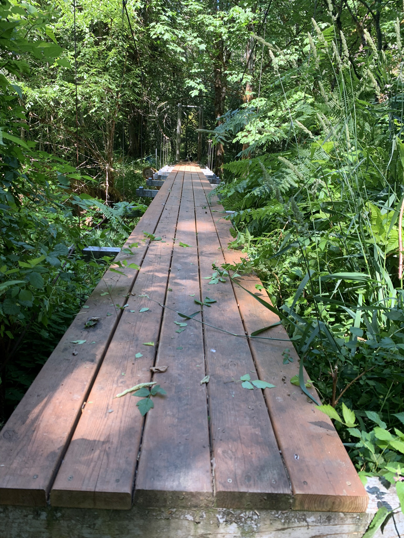
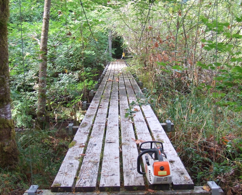
February 25, 2019 was a very bad day for our 80′ suspension bridge that we built in 2005. Part of a large maple tree that was weighted down with heavy snow decided to break and fall directly on one of the support posts on the other side of the creek, bringing lots of other trees along with it. Once it thawed and we could clean up the mess, we assessed the damage. We had to replace the post and raise the bridge again. You can read about that here. The next step was to replace the decking and adjust the suspender cables.
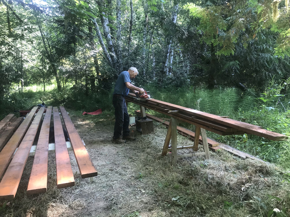
This summer I finally carved out time to get it done. To note, the old decking had already been recycled three times. The untreated fir was originally pulled from a deck from a remodel job and used as a deck in front of my shop. It stayed there for about twenty years before several boards got so bad I decided to pull the whole thing apart and save what was still good and send the rest away. By the way, I used the concrete piers from that deck as foundation for our yurt, which you can read about here.
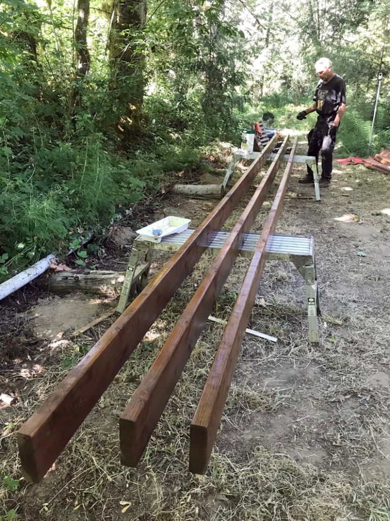
The decking held up very well all things considered. We scraped most of the moss off and usually kept the leaves raked, but it was already overdue to be replaced when the bridge was hit. While we originally hoped to use some kind of metal for our “final” deck, we decided to use pressure treated dock boards. I put a coat of water sealant on all sides just to give the boards a bit more protection.
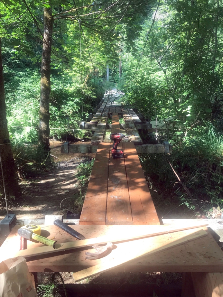
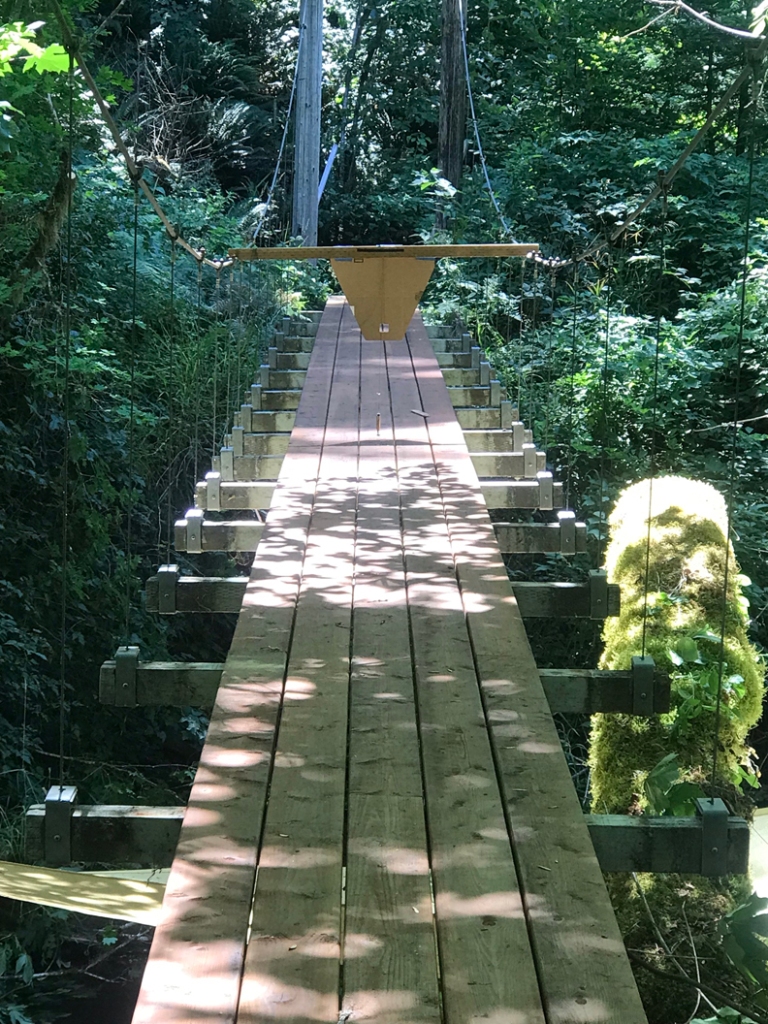
The original decking consisted of six 2×6 boards spaced about an inch apart. I decided to change both the number of boards in the span and the spacing. This made for a more than adequate deck to cross and would help keep moss from getting between the boards. But it created some difficulty in the replacement process. Instead of just removing boards and replacing them, I had to start over and work carefully while working about 12 feet up from the creek bed. I wasn’t as young as I was when I installed the first deck in 2005…
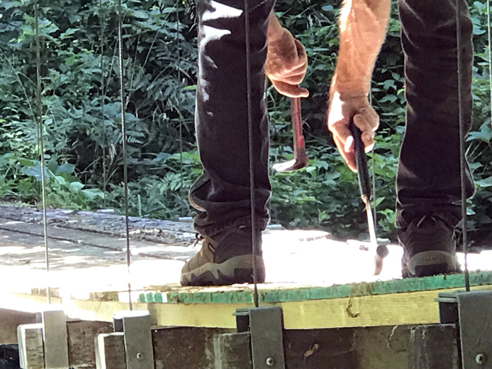
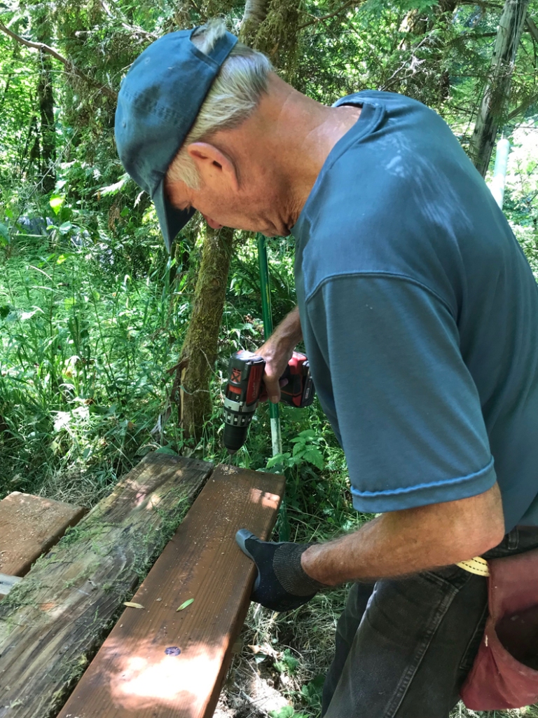
The hardest part of the process was removing the old decking. The metal screws had rusted because of the interaction between them and the pressure-treated support beams. So, a lot of them didn’t come out without a fight.
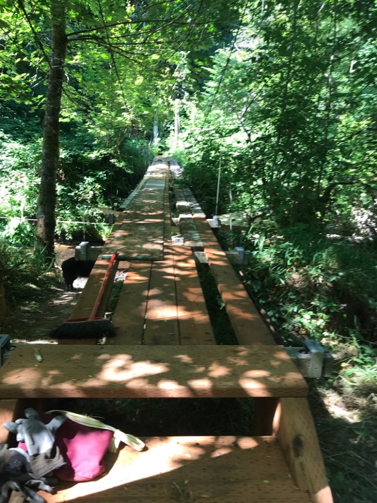
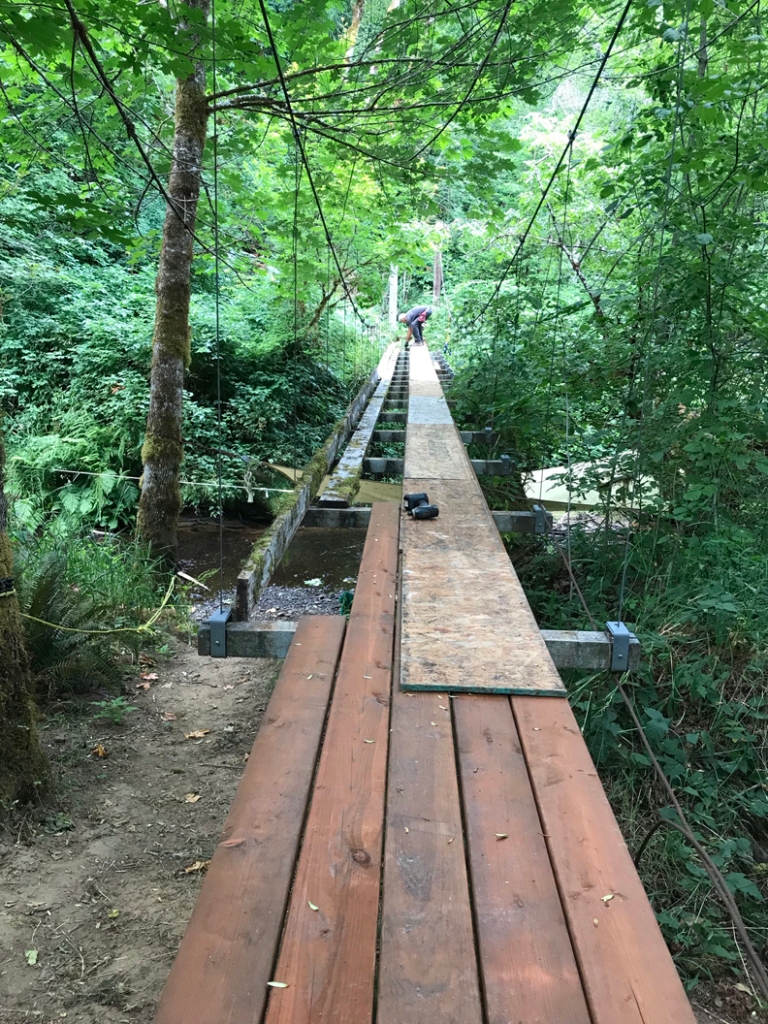
At first, I planned to build as I moved along, but soon decided that it made more sense to do the center run (of 5) first, then down one side and then down the other, using plywood planks on top of the old damaged decking for stability. I cut the pieces in pretty much the same pattern as before.
Here is what I did at first, but decided working one side then the other made more sense, and was safer.
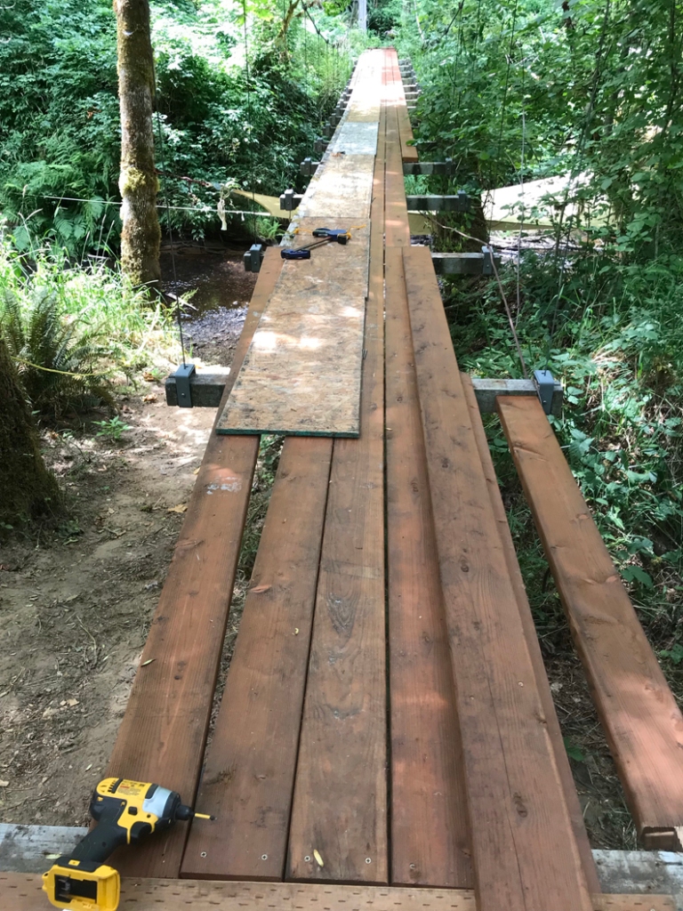
Once I got going, the process took about a week of not working full-time. I worked pretty much alone, though Robin did most of the treatment of the new boards.
I pre-drilled for the screws just to make things go a little faster. The old boards were piled nearby. Amazingly, many of them still have some life left in them! But I won’t use them for another bridge.
Once completed, I needed to level up the deck. I had waited until this work was done to really tighten things back up after we replaced the post that was destroyed in the storm. The deck had a twist in it, partly from the hit and partly from hanging sideways for about nine months.
Because the post was broken in half and the deck twisted sideways, it pulled the opposite post inward. This caused the suspender cables to misalign. Once the posts are brought into alignment and opposing suspenders are both vertical, then tension can be adjusted to bring the deck up and level.
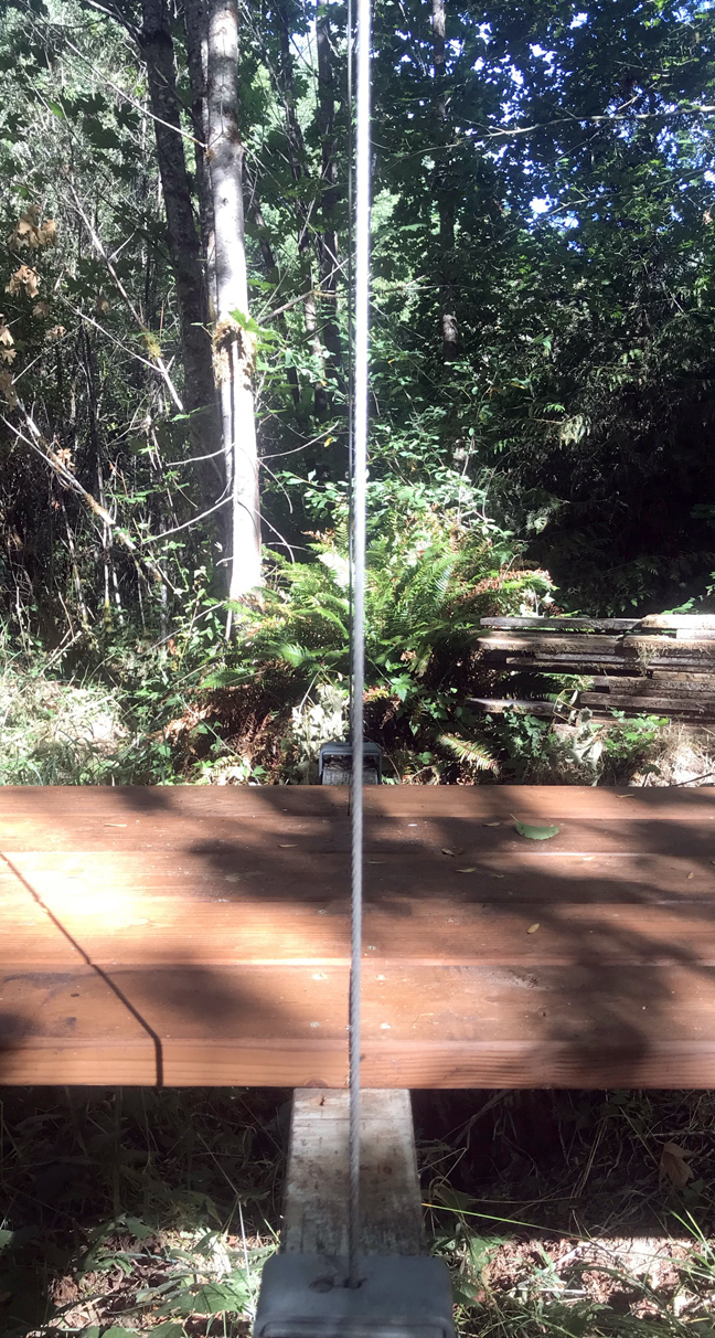
Looking across the support beam, the cable in front is vertical but the one across is “leaning.” This is an “after” photo; I forgot to take one before I fixed them.
I devised a “level” of sorts by taking a piece of wood long enough to ride over both cables, a wooden level. On that level, a piece of cardboard was securely attached. A line being perpendicular to the bottom edge of the “level” wood piece was then drawn across the cardboard to create a center line of the level and cardboard. It was boldly marked so it could be seen from a distance. A plumb-bob was then attached directly on the centerline. When the deck was adjusted so that the plumb-bob line matched up to the line drawn on the cardboard the deck would be level. I adjusted the deck by tightening the turnbuckles. You can read about that process here.
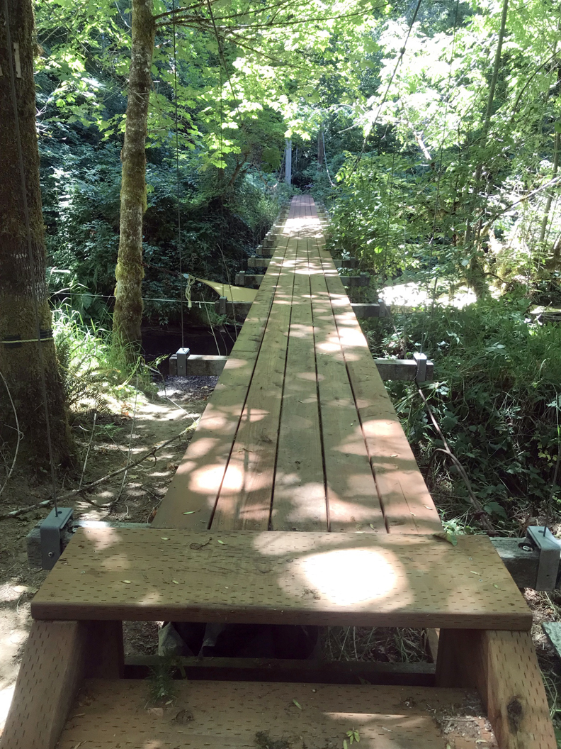
So, in all the pole was replaced, the steps were replaced, the decking was replaced, the suspender cables realigned, and the deck was leveled. There are not many big trees left that are aimed at the bridge, but we’ll see what nature brings next. Hopefully we’ll be ready.
The bridge helps to shade our favorite beach spot in the summertime. It’s hard to believe that little creek gets up to about one foot under the bridge during flood season, but it does!
Thanks for stopping by. Be sure to check out our books about building a yurt or a small cable suspension bridge. The links to purchase are on the introductory page:
Images, diagrams, and text copyright 2013-2021 by Marvin Denmark unless otherwise noted. Please do not copy and post my content anywhere without my permission. Thank you.
I got a question on Facebook recently from a cable suspension bridge builder and enthusiast. In short it asks when do I apply tension to the cables.
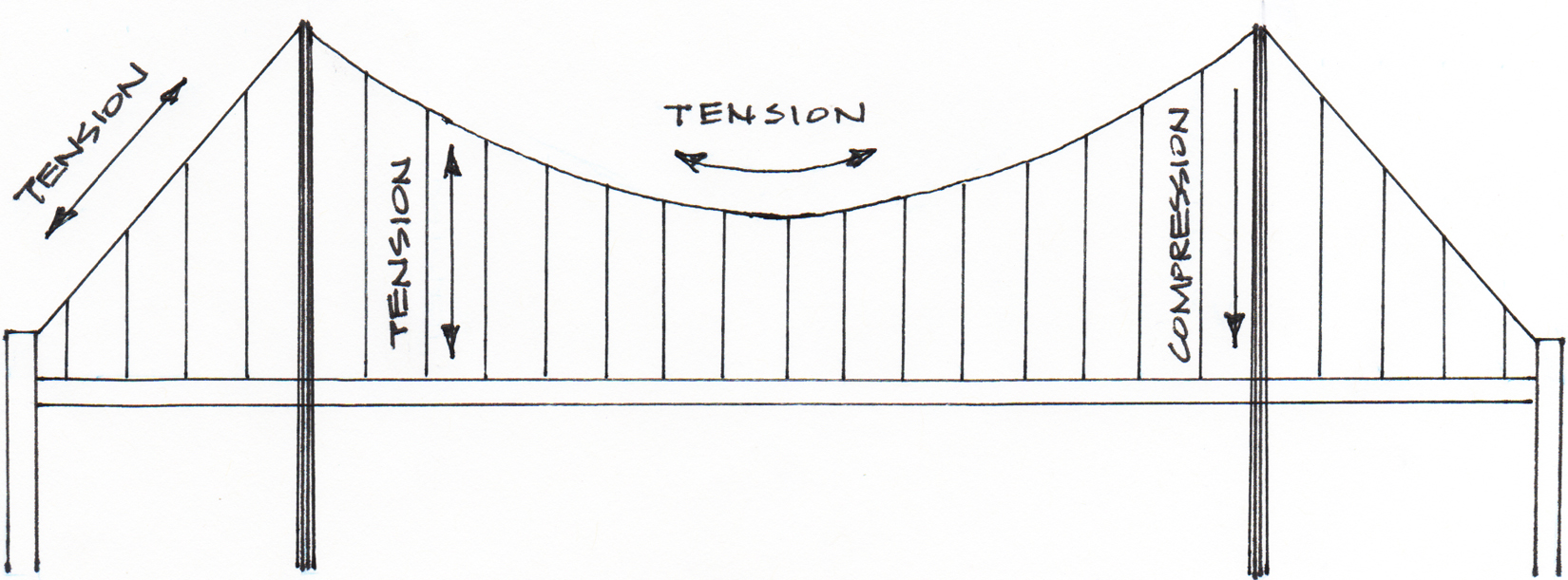
To answer this I want to back up a bit and talk about cable bridges. These bridges fall under the area of physics called “statics”. Statics deals with objects that aren’t accelerating. In short, all forces are in equilibrium. [If a bridge is moving “downward” it is most likely failing.]
The physics of equilibrium: in the cable bridge there are three force vectors involved; a gravitational downward pull and two angular tensions upward that hold the gravitational pull in check. To get to the sum of the gravitational pull one has to account for all of the live and dead loads imposed on the bridge. So you total all of the materials and the people/things to be “moved” across it. To be precise you are totaling all of the masses of the materials/things. This is then multiplied by gravitational acceleration in the formula ( f = ma ). We can substitute “weight” of things [You weigh what your mass is pulled down by gravity] for the “mass X gravity” in the equation for our purposes since we are working with near-to-earth calculations. Thus we have our downward force vector.
Once you have the downward force you can determine the two tension vectors. Assuming you are “in the middle” of the bridge with your calculations the two tensions will be equal and each one-half the gravitational pull. Keep in mind that you have two cables to make a bridge. Loads would be divided between them.
With the tension value you can go to a cable manufacturing site and find a cable size suitable for the load. Cable bridges are designed with a 5 to 1 safety ratio. That is to say if you have a tension value of 1 you will choose a cable with a tension value five times that.
Those tension values also help you design the size/weight of the dead man. The dead man needs to resist the upward pull the cable has created when passing over the posts. Finally the posts must withstand the total of the loads of the bridge.
Back to the question: when should I tension the cables? The short answer is you already have. In your design you specified some drop in your cable, did all your calculations and determined how everything was to be placed and connected. As the saying goes, “it’s already baked into the pie”.
An engineer designing a cable suspended bridge would do much more specific, detailed, and accurate calculations to arrive at a solution. These bridges are a public structure with safety issues and an intended long life. Because of this all sorts of factors are investigated, such as earthquakes, tsunamis, floods and high wind events. I present only a simplified version. If these kinds of problems interest you, maybe you will be a bridge designer.
Thanks for stopping by. Be sure to check out our books about building a yurt or a small cable suspension bridge. The links to purchase are on the introductory page:
Images, diagrams, and text copyright 2013-2021 by Marvin Denmark unless otherwise noted. Please do not copy and post my content anywhere without my permission. Thank you.
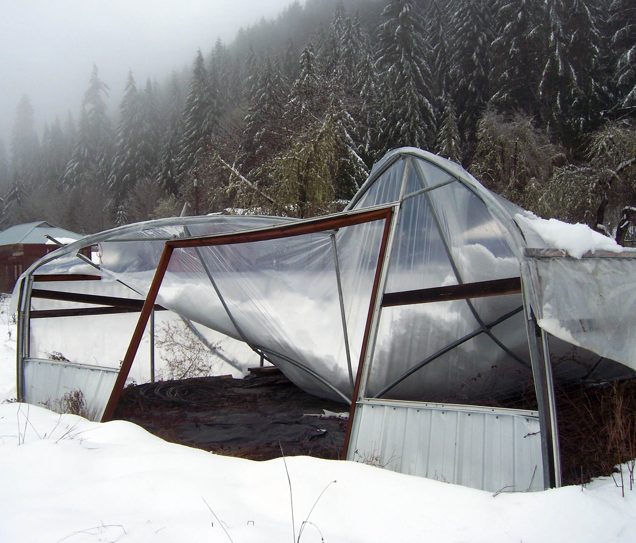
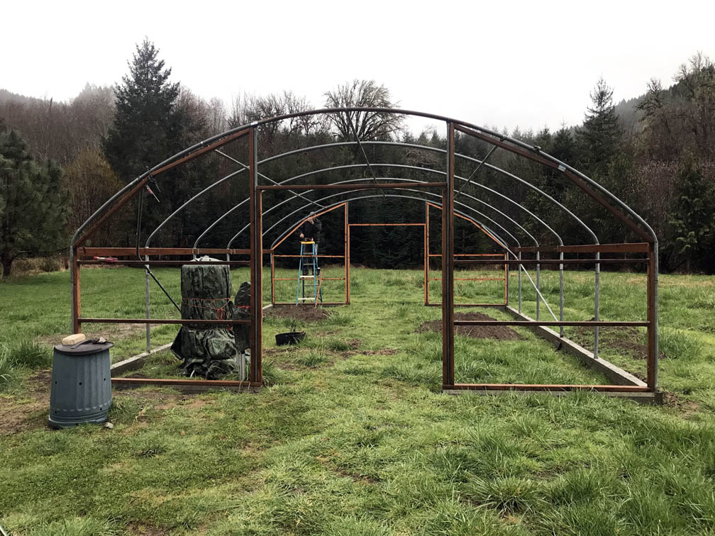
We purchased most of the parts for another 24′ greenhouse from a yard sale and installed it in 2009 or thereabouts. We never really put it to use, then a heavy snow and ice storm came along and that was the end of it. We were still building our house in 2014 and so put off rebuilding. Meanwhile, I decided on a purpose for the next one: aquaculture. I’ll mix growing fish with growing plants, along with chickens and a small worm farm.
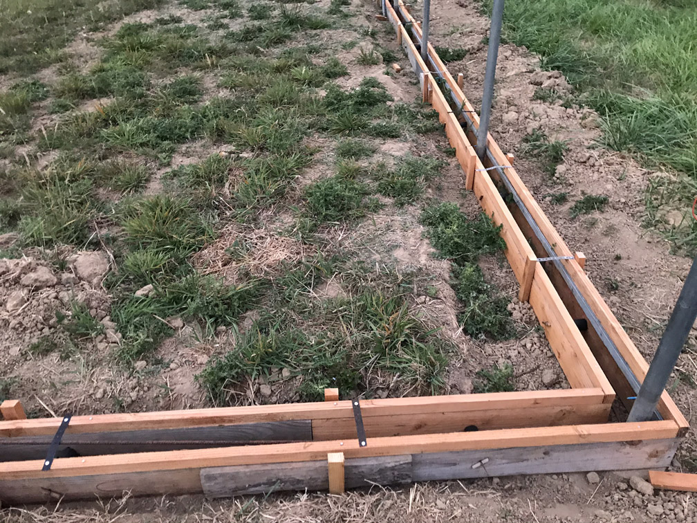
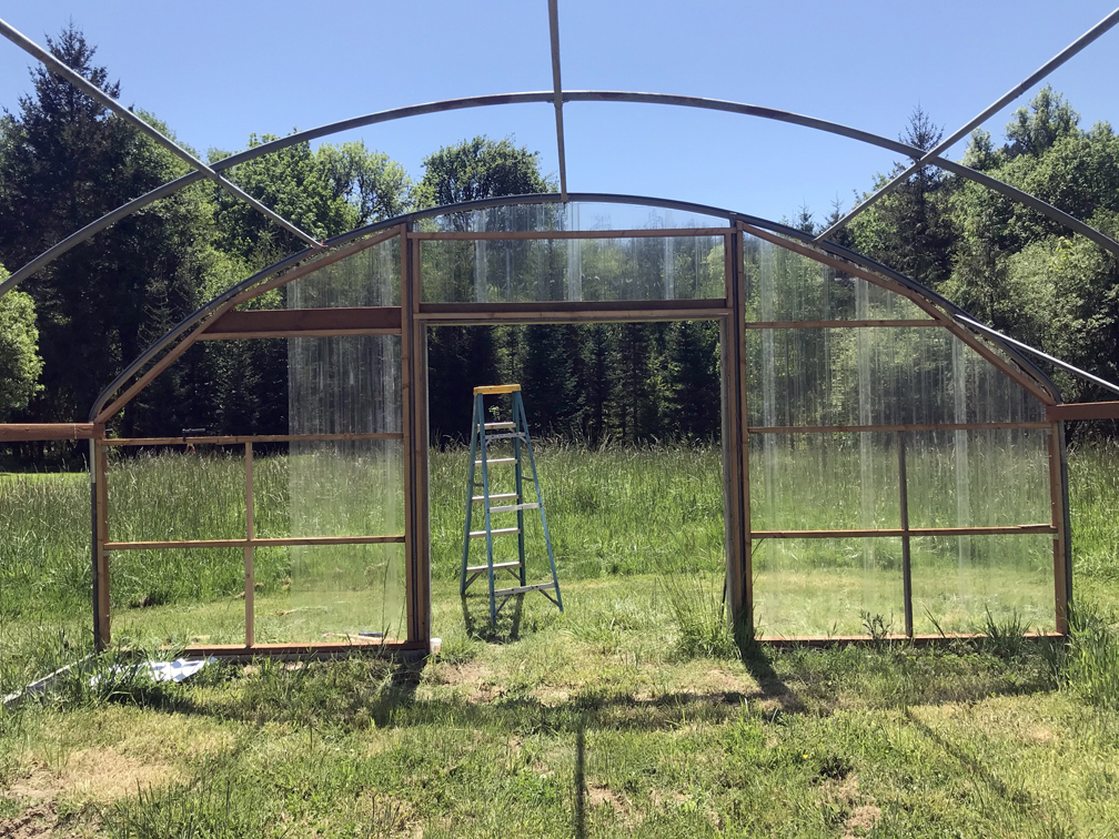
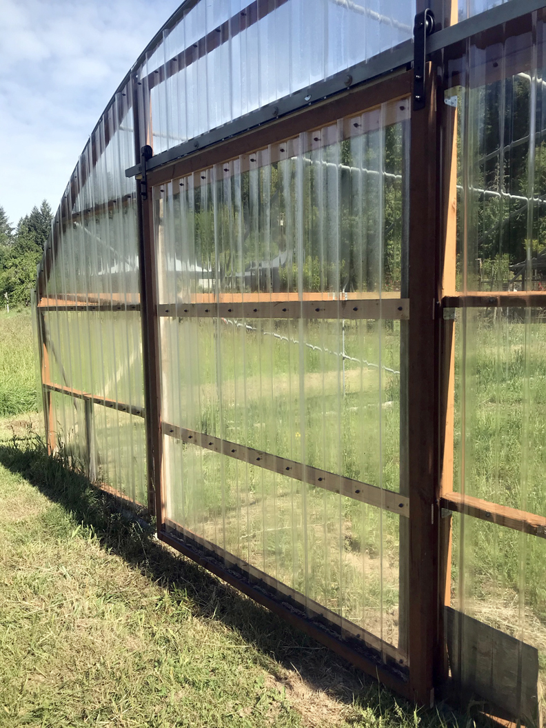
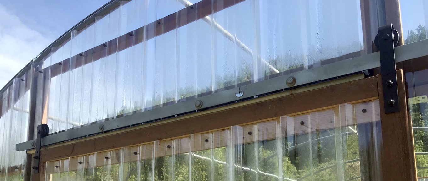
So, armed with a goal, I sorted through the usable parts from the wrecked greenhouse, acquired a few more, and got to work. I’m at the point where we’re about ready for the plastic covering, once I install the tracking system for the squiggle wire that holds the plastic in place. Here are photos of the progress from beginning to where I am with it today:
As you can see, I built sliding barn doors for the north and south ends – double doors on the north and a single slider on the south. Once it’s covered, we’ll see about installing the fish tanks and getting all that set up using the farm spring water. Stay tuned!
Thanks for stopping by. Be sure to check out our books about building a yurt or a small cable suspension bridge. The links to purchase are on the introductory page:
Images, diagrams, and text copyright 2013-2021 by Marvin Denmark unless otherwise noted. Please do not copy and post my content anywhere without my permission. Thank you.
Don’t fret. Here is a reasonably easy why to turn a table leg so it has a rounded end. Then you won’t be forcing a square peg into a round hole. I’ll also describe how I made a small bedside stand using this method for the legs.
First thing, what dimension is the leg? — Say it’s 1-1/2″ X 1-1/2″ as was mine. The resultant diagonal dimension would be 2.12″ (or 2 and about 1/8 inch). I had already “edged” the corners slightly so my diagonal was just at 2″. I then cut a 12″ section of electrical conduit that had an interior dimension of 2″ (ABS plumbing waste pipe is another option). The leg was then inserted within the conduit, with thin cardboard pieces placed on the leg corners to wedge it in snug. These photos were taken later, but shows the step I’m describing.
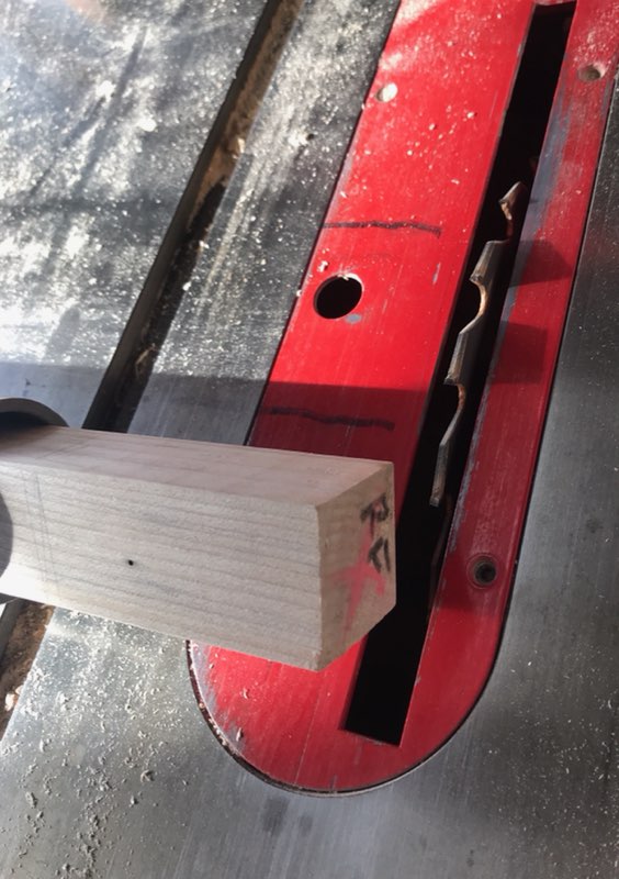
The table saw fence is positioned such that the distant side of the blade would just slice at the point that is the longest length of the leg which would touch the underside of the table top piece.
The blade has been set to the height that would allow the blade to just touch the flat sides of the leg surface of it’s four sides. The leg is 1-1/2″ so my rounding will make the end that dimension. The blade could be adjusted to any height to get a smaller rounded end. The leg-in-conduit is then run back and forth over the blade. The corners are carved down first. The leg-in-conduit can then be slid side to side over the highest portion of the blade. Believe it or not, this method took about the same amount of time as setting up and dealing with a lathe.
The next step is to cut the shoulders of the square to round on the legs. When cleaned up the round surfaces can be rasped/filed to smooth them.
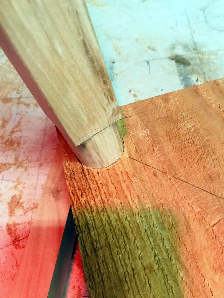
I checked my dimensions with a caliper and lastly tested them out in a mock hole before putting all the parts together for a final fit.
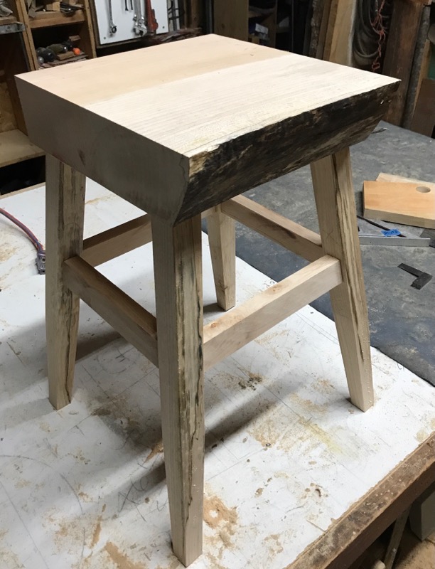
Now to the table project. There aren’t any process photos but the instructions are pretty straight-forward. I was building a small bedside stand for Robin. I didn’t plan this out much. Just an idea that followed from a small length/width, but quite thick (3-1/4″) piece of maple. To begin with I had thought the legs would be vertically straight down. But, Robin introduced a problem. She had a basket that held our dog Jeep’s toys that needed to go beneath the stand and between the legs. That meant the legs needed to splay outward going down.
After more or less squaring up and preparing the top, I made the legs as described above. A piece of spalted maple served for them. With the problem of having to put a basket underneath, I decided to just lay the legs (one side) out as if they were attached at the top. My work table has a white surface, so when the legs were laid out with a taper such that the basket (width dimension) could fit between I could mark around them. I measured the bottom (spread) dimension and then traced the edges out to find the taper angle. In this case it was 8 degrees.
Next was making the stretchers (the 4 horizontal pieces that attach the legs) also of maple. The lengths came from my traced drawing. I cut a tenon by running passes on the table saw at each end on both side faces on all of them. Then I drilled out a mortise on the legs to receive the tenon. After some chiseling and hand carving to finish them the stretcher and legs were ready for assembly.
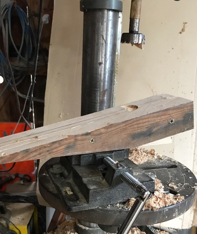
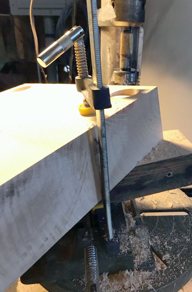
The last major task for assembly was to drill the holes that the leg dowel end would be inserted. The holes had to be drilled at an angle so I had to make a jig of the appropriate angle that could be stable and level across it surface. The legs tapered from the top at 8 degrees at front to back and from side to side. Question: what is the angle that the holes should be drilled? (Answer in an upcoming post. Hint: it’s trigonometry).
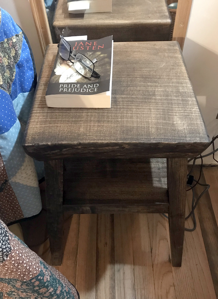
After a final sanding, a dark walnut stain was applied and it was ready for a “dry” assembly. Before I put it together I had thought it might be difficult to get the legs into the drilled holes. As it turned out there was sufficient play in the stretchers to legs so that the dowel end went right in. The whole assembly could then be tightened with clamps. The final step then was gluing and assembling. That was done and excess glue was wiped off, job done.
Epilogue: I goofed up the basket height measurement and the basket wouldn’t fit under the stand. I think had I tried to accommodate the extra height the taper of the legs would be too great. Jeep was cool with it. His basket moved to a nearby location.
Thanks for stopping by. Be sure to check out our books about building a yurt or a small cable suspension bridge. The links to purchase are on the introductory page:
Images, diagrams, and text copyright 2013-2020 by Marvin Denmark unless otherwise noted. Please do not copy and post my content anywhere without my permission. Thank you.