
Off and on we receive requests for the cable locking system (CLS); either the parts or for dimensions. As we have stated before, we could not produce/have manufactured, store and handle/ship the parts at a reasonable cost to the buyer, so we do not provide them for sale. While all of this information is in the book or in previous blogs, we thought we would try to break down the method for sizing of the CLS so interested bridge builders could use the information to have their parts manufactured close to home.
Refer to the drawing below to picture the description that follows.
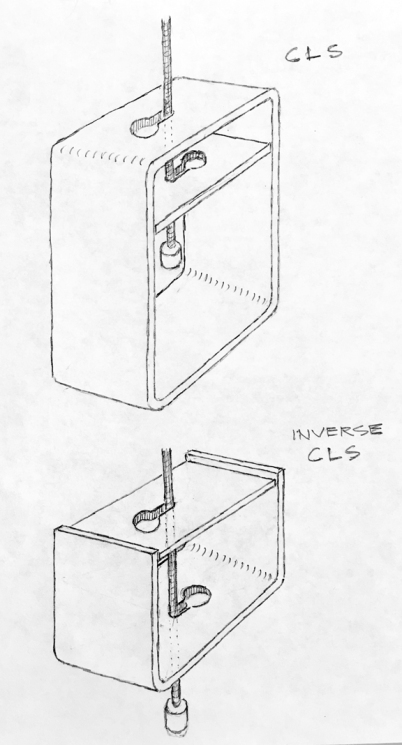
The main body of the CLS was made from a section of rectangular steel tube of 4″ X 5″ outside diameter, the section being 1-3/4″ wide. The wall thickness was .17 of 1 inch, which is very close to 3/16″. The interior was therefore close to 3-5/8″ by 4-5/8″, which fits nicely with a 4X4 (nominal) piece of lumber. So that defines the main body of the device. [After my project, I now would recommend using a 4″ X 6″ tube for the extra room for maneuvering the cable during assembly.] There is a locking plate that fits inside of the main body. It is also .17 of an inch (3/16″) and is sized to fit just inside, at 3-9/16″.
The location of the keyhole is placed in this method: the keyhole is composed of a large hole with a smaller slot. If you picture the end of that slot as a hole of the dimension of the suspending cable, that hole would be placed in the exact center of one of the 4″ ends of the rectangular tube, the remaining keyhole would point towards one of the tube’s edges. The locking plate is treated similarly.
The dimensions for the keyhole are determined by making them slightly larger than the materials passing through. Since the suspending cable is 3/16″ the hole was enlarged by 1/32″, thus the hole was drilled at 7/32″. For the large end of the keyhole the dimension of the stop was the guiding size. The aluminum cable stops once crimped on measured 1/2″, which is enlarged by 1/16″ to allow for easy passage of the stop through both plates of metal. So that hole is drilled at 9/16″. There is nothing imperative about these drilled dimensions. If you use different materials than you adjust the holes accordingly.
For the inverse CLS, [picture in your mind] you simply need to cut off the bottom half of the 4X5 steel tube section. You now have essentially a section of steel C channel of 4″ width, with 2 1/2″ flanges. Now mirror-image this remaining half. You should have it placed beneath the 4X4 beam, cradling it. This changes the CLS from a tension device to a compression device, but the plates function in the same manner as before. All sizing remains the same. What does change is that you have to drill a 5/8″ hole (insert an anti-corrosion vinyl tube in hole) in the 4X4 beam so the suspending cable can pass through to access the inverse CLS.
As we have said before, you may freely use this information to build your own bridge or your friend’s bridge. But if you want to mass produce these parts please contact us regarding licensing.
Thanks for stopping by! Be sure to check out our bridge book if you’re thinking about building (or just reading about building) a DIY cable suspension bridge. Here is the link: Building a Small Cable Suspension Bridge with the Cable Locking System
Images, diagrams, and text copyright 2018 by Marvin Denmark unless otherwise noted. Please do not copy and post my content anywhere without my permission. Thank you.
